Toshiba Tecra M9 PTM90C-TG609C Users Manual Canada; English - Page 46
Indicators, System indicators
 |
View all Toshiba Tecra M9 PTM90C-TG609C manuals
Add to My Manuals
Save this manual to your list of manuals |
Page 46 highlights
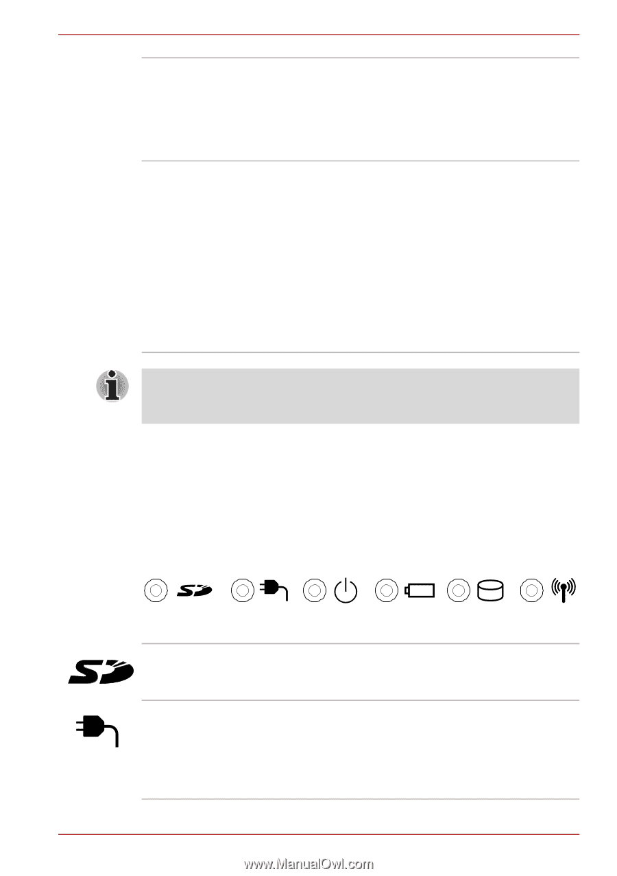
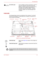
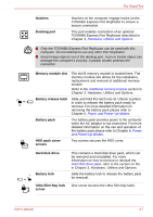
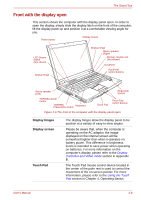
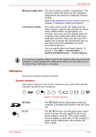
The Grand Tour Memory module slot The slot A memory module is located here. The memory module slot allows for the installation, replacement and removal of additional memory module. Refer to the Additional memory module section in Chapter 3, Hardware, Utilities and Options. LCD Sensor switch This switch senses when the display panel is either closed or opened and activates the Panel Power Off/On feature as appropriate. For example, when you close the display panel the computer enters Hibernation Mode and shuts itself down and then, when you next open the display, the computer will automatically start up and return you to the application you were previously working on. You can specify within the Power Options. To access it, click Start -> Control Panel -> System and Maintenance -> Power Options. Do not put any magnetic objects close to this switch as they may cause the computer to automatically enter Hibernation Mode and shut down even if the Panel Power Off feature is disabled. Indicators This section explains indicator functions. System indicators LED system indicators next to their respective icons, glow when specific computer operations are in progress. SD Card DC IN User's Manual Figure 2-7 System indicators The SD Card indicator glows green when the computer is accessing the device in the SD Card slot. The DC IN indicator normally glows green when power is being correctly supplied from the AC power adaptor. However, If the output voltage from the adaptor is abnormal, or if the computer's power supply malfunctions, this indicator will flash orange. 2-10
-
 1
1 -
2
-
3
-
4
-
5
-
6
-
7
-
8
-
9
-
10
-
11
-
12
-
13
-
14
-
15
-
16
-
17
-
18
-
19
-
20
-
21
-
22
-
23
-
24
-
25
-
26
-
27
-
28
-
29
-
30
-
31
-
32
-
33
-
34
-
35
-
36
-
37
-
38
-
39
-
40
-
 41
41 -
 42
42 -
 43
43 -
 44
44 -
 45
45 -
 46
46 -
 47
47 -
 48
48 -
 49
49 -
 50
50 -
 51
51 -
52
-
53
-
54
-
55
-
56
-
57
-
58
-
59
-
60
-
61
-
62
-
63
-
64
-
65
-
66
-
67
-
68
-
69
-
70
-
71
-
72
-
73
-
74
-
75
-
76
-
77
-
78
-
79
-
80
-
81
-
82
-
83
-
84
-
85
-
86
-
87
-
88
-
89
-
90
-
91
-
92
-
93
-
94
-
95
-
96
-
97
-
98
-
99
-
100
-
101
-
102
-
103
-
104
-
105
-
106
-
107
-
108
-
109
-
110
-
111
-
112
-
113
-
114
-
115
-
116
-
117
-
118
-
119
-
120
-
121
-
122
-
123
-
124
-
125
-
126
-
127
-
128
-
129
-
130
-
131
-
132
-
133
-
134
-
135
-
136
-
137
-
138
-
139
-
140
-
141
-
142
-
143
-
144
-
145
-
146
-
147
-
148
-
149
-
150
-
151
-
152
-
153
-
154
-
155
-
156
-
157
-
158
-
159
-
160
-
161
-
162
-
163
-
164
-
165
-
166
-
167
-
168
-
169
-
170
-
171
-
172
-
173
-
174
-
175
-
176
-
177
-
178
-
179
-
180
-
181
-
182
-
183
-
184
-
185
-
186
-
187
-
188
-
189
-
190
-
191
-
192
-
193
-
194
-
195
-
196
-
197
-
198
-
199
-
200
-
201
-
202
-
203
-
204
-
205
-
206
-
207
-
208
-
209
-
210
-
211
-
212
-
213
-
214
-
215
-
216
-
217
-
218
-
219
-
220
-
221
-
222
-
223
-
224
-
225
-
226
-
227
-
228
-
229
-
230
-
231
-
232
-
233
-
234
-
235
-
236
-
237
-
238
-
239
-
240
 |
 |