Tripp Lite 0SU70032 Quick Start Guide for 0SU70030 / 0SU70032 KVM Switches 933 - Page 1
Tripp Lite 0SU70032 Manual
 |
View all Tripp Lite 0SU70032 manuals
Add to My Manuals
Save this manual to your list of manuals |
Page 1 highlights
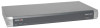
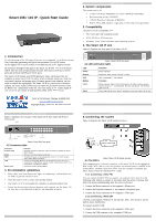
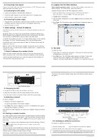
Smart 108 / 116 IP - Quick Start Guide 1. Introduction To take advantage of the full range of features, we recommend you read the softcopy User Guide after performing the Quick Start procedure. It's in PDF format on the supplied CD or on our website www.minicom.com in the Support section. All references throughout this guide to the Smart 116 IP refer equally to the Smart 108 IP. The two units are functionally the same. The Smart 116 IP has 16 Server ports and the Smart 108 IP has 8 Server ports. The Smart 116 IP extends your KVM (keyboard, video, and mouse) from any computer or server over TCP/IP via LAN, WAN or Internet connection. Now you can control, monitor and manage up to 16 remote servers from wherever you are, inside or outside the organization. The Smart 116 IP is a cost-effective hardware solution, for secure remote KVM access & control of 16 computers/servers from the BIOS level - independent of the OS. One local analog or one remote digital IP user can access and control 16 multi-platform (PS/2, SUN, USB) servers. 1111 W. 35th Street, Chicago, IL 60609 USA www.tripplite.com/support Copyright ©2012 Tripp Lite. All rights reserved. QUICK START GUIDE Figure 2 illustrates the rear panel of the Smart 116 IP. The Smart 108 IP has 8 Server ports. Monitor I CONSOLE 0 SERIAL 9 10 11 12 13 14 15 16 POW ER 100-240 VAC 50/60 Hz Mouse Power Keyboard connector FLASH LAN 1 2 3 4 5 6 7 8 Flash (download) LAN (Ethernet) connector connector Server ports Figure 2 Smart 116 IP rear panel 4.2 Connector table Connector Console KVM Serial Flash LAN Server ports Function (Optional) Connect a keyboard, video and mouse to operate the Smart 116 IP locally This port is for future Serial functionality To update firmware of the analogue part of the Smart 116 IP system OSD, Switch, RICCs and RoCs. Connect to 10/100 Mbit Ethernet. Green LED illuminates when unit is connected to a 100 Mbit/sec network. Yellow Led illuminates when unit is connected to a 10 Mbit/sec network. Connect to servers via RICC/ROCs 5. Pre-installation guidelines • Place cables away from fluorescent lights, air conditioners, and machines that are likely to generate electrical noise • Place the Smart 116 IP on a flat, clean and dry surface • The Smart 116 IP is not intended for connection to exposed outdoor lines • Ensure that the maximum distance between each computer and the Smart 116 IP, does not exceed 10m/33ft for RICCs and 30m/100ft for ROCs. 2 SMART 108 / 116 IP 2. System components The system consists of: • 1 Smart 116 IP (p/n 0SU60005) or 1 Smart 108 IP (p/n 0SU70032 • Rack mounting set (p/n 5AC20247) • 1 RS232 Download cable (p/n 5CB40419) • ROCS - PS/2, USB. (Ordered separately). CAT5 cables (1.5m provided) 3. Compatibility The Smart 116 IP is compatible with: • PS/2, SUN and USB computers/servers • VGA, SVGA, or XGA monitors • Windows, Linux, UNIX and other major operating systems 4. The Smart 116 IP unit Figure 1 illustrates the front panel of the Smart 116 IP. MINICOM SMART 116 IP Power Remote Link Figure 1 Smart 116 IP front panel 4.1 LED and button table Local Reset LED Power Remote Link Button Local Reset Function Power Indicator Illuminates when remote session is active Unit is connected to the network Function When pressed, Smart 116 IP disconnects the Client remote session and the local mouse and keyboard become operational. The Remote LED turns off. Press and hold for more than 7 seconds to reset the Smart 116 IP unit 1 SMART 108 / 116 IP 6. Connecting the system Figure 3 illustrates the Smart 116 IP system overview. I 0 POW ER 100- 240 VAC 50/60 H z CON SOL E SER IAL 9 10 11 12 13 14 15 16 FL ASH L AN 1 2 3 4 5 6 7 8 To LAN port Remote User Internet / VPN / LAN To servers ROCs 6.1 The ROCs Figure 3 Smart 116 IP system overview Each computer/server is directly connected to the Smart 116 IP via the appropriate ROC using CAT5 cable in a star configuration. No external power is needed at the remote ROCs. The ROCs draw their power from the computer's keyboard port (ROC PS/2) or from the USB port (ROC USB). 6.1.1 Connecting a ROC PS/2 You can connect the ROC PS/2 to a powered on computer, but it must be in the following order. Failure to connect in this order while the server is running, may lead to the mouse malfunctioning until the server is rebooted. 1. Connect the Mouse connector to the computer's Mouse port. 2. Connect the Keyboard connector to the computer's Keyboard port. 3. Connect the Screen connector to the computer's Video port. 6.1.2 Connecting a ROC USB The ROC USB supports Windows 98 SE and later, MAC, SUN and SGI, and all modern Linux distributions. To connect the ROC USB: 1. Connect the Screen connector to the computer's Video port. 2. Connect the USB connector to the computer's USB port. 3
-
 1
1 -
 2
2
 |
 |