Tripp Lite B098048 Quick Start Guide for Console Servers English - Page 2
Package Includes, B098-016-V Model Only, Hardware Assembly
 |
View all Tripp Lite B098048 manuals
Add to My Manuals
Save this manual to your list of manuals |
Page 2 highlights
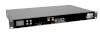
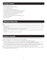
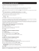
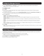
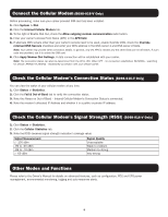
Package Includes • B098-Series Console Server • (x2) C13 to NEMA 5-15P Power Cords, 6 ft. • (x2) Cat5 Patch Cords, 6 ft. • (x1) 2.4 GHz SMA Wi-Fi Diversity Antenna • (x1) B090-A9F Straight-Through Serial Adapter (DB9 to RJ45 F/F) • (x1) B090-A9F-X Crossover Serial Adapter (DB9 to RJ45 F/F) • (x1) B090-A9M Modular Serial Adapter (DB9 to RJ45 M/F) • (x2) Cellular Antennas (B096-016-V only) • (x1) Magnet-based Coaxial Extension Cable (B096-016-V only) • Rack-Mounting Hardware • Quick Start Guide B098-016-V Model Only B098-016-V Cellular Model: Follow the steps below before moving on to the Hardware Assembly section of this Quick Start Guide. 1. Using the included Cellular Antennas, screw the first antenna to the CELL (MAIN) and the other to CELL (AUX) for increased signal strength. Note: If you have purchased a GPS antenna, screw it onto the connector labeled GPS. If cellular strength is an issue, use the included 10 ft. magnet-based coax extension cable for mounting outside of the rack. 2. Insert your carrier-provided Mini-SIM Card into the SIM Card slot. Insert until a click is heard ensuring the card is locked into place. Note: Insert your Mini-SIM Card with the contacts facing down. Hardware Assembly 1. If rack-mounted: Attach the included rack-mounting kit to the sides of the console server to be fixed onto the rack. 2. Connect the NET1 port on the console server to your primary network. 3. Connect the NET2 port on the console server to your Out-of-Band (OOB) management network. Note: The B098-Series also includes Small Form-Factor Pluggable (SFP) ports for NET1 and NET2 fiber-optic connections. If an SFP module is plugged in and establishes a working link, the SFP port will activate and the paired RJ45 port will deactivate. 4. For Out-of-Band (OOB) dial-in access, plug an RJ11 cable into the front-facing RJ11 port to connect to the built-in V.92 modem. Plug the other end of the RJ11 cable into a functioning landline port to allow the B098's V.92 modem to dial-out. 5. Connect additional devices to the console server's serial ports (RJ45), USB 3.0 ports and SD card slot. 6. Power on the console server by connecting the included C13 to NEMA 5-15P power cords to the built-in Dual Universal AC power supplies (with automatic failover). 2
-
 1
1 -
 2
2 -
 3
3 -
 4
4 -
 5
5 -
 6
6 -
 7
7 -
 8
8
 |
 |
