Tripp Lite SMART2200NET Owner's Manual for SmartProNET/SmartProXL UPS 931310 - Page 4
Basic Operation - tripp
 |
View all Tripp Lite SMART2200NET manuals
Add to My Manuals
Save this manual to your list of manuals |
Page 4 highlights
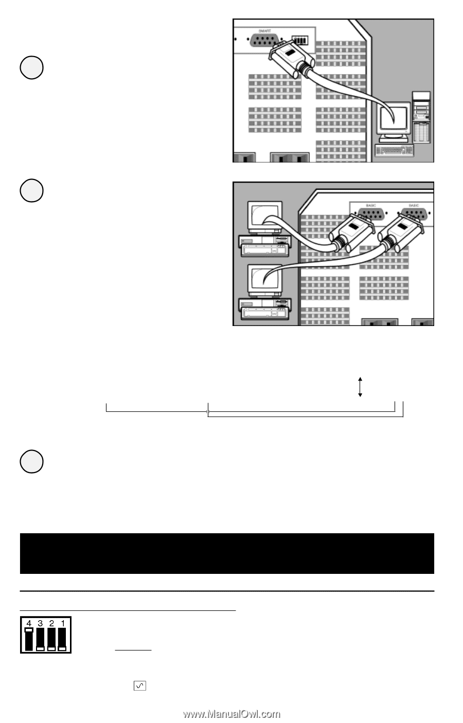
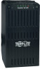
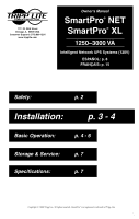
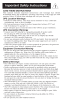
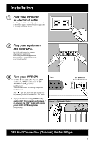
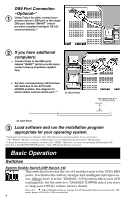
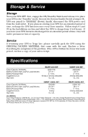
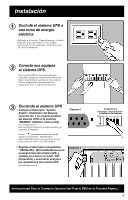
DB9 Port Connection -Optional-* 1 Using Tripp Lite cable, connect your primary server's DB9 port to the single DB9 port labeled "SMART" (which provides complete intelligent RS-232 communications).** 2 If you have additional computers: a. Connect them to the DB9 ports labeled "BASIC" (which provide basic, contact-closure shutdown capabilities). b. Set their corresponding LAN Interface DIP Switches to the ACTIVATE (DOWN) position. See diagram for which switch controls which port.*** 2a. Back Panel DIP Switches #2 & #1 (Lan Interface Switches) DEACTIVATE ACTIVATE 2b. Back Panel 3 Load software and run the installation program appropriate for your operating system. * Serial port connections are optional. Your UPS will function properly without these connections. ** The "SMART" DB9 port is always enabled and is not controlled by the LAN Interface DIP Switches. *** If you do not connect a computer to either of the "BASIC" DB9 ports, set their corresponding LAN Interface DIP Switches to the DEACTIVATE (UP) position. Note: DIP Switch #3 has no function. Basic Operation Switches System Enable Switch (DIP Switch #4) This switch is located in the set of 4 switches next to the UPS's DB9 ports. It activates the battery charger and intelligent microprocessor. Always leave it in the "ENABLE" (UP) position when your UPS is plugged in. Set the switch to "DISABLE" (DOWN) only if you store or ship your UPS (to reduce battery drain). Note: the "XXX" light will flash until you engage the ON/Standby Switch to activate the "ON" mode (power ON at the UPS receptacles). 4
-
 1
1 -
 2
2 -
 3
3 -
 4
4 -
 5
5 -
 6
6 -
 7
7 -
 8
8 -
 9
9 -
 10
10 -
11
-
12
-
13
-
14
-
15
-
16
-
17
-
18
-
19
-
20
 |
 |