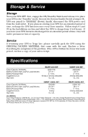
Tripp Lite SMART2200NET Owner's Manual for SmartProNET/SmartProXL UPS 931310 - Page 6
Other UPS Features
 |
View all Tripp Lite SMART2200NET manuals
Add to My Manuals
Save this manual to your list of manuals |
Page 6 highlights
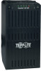
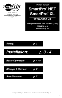
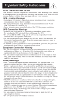
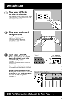
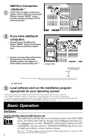
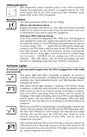
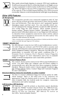
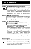
This multi-colored light displays 4 separate UPS load conditions. It will turn from green (low) to yellow (medium) to red (high) as you connect equipment to show you the load level your UPS is supporting. When the light is red your UPS is supporting a load above 85% of its capacity. If the red light begins flashing, your UPS is severely overloaded. Remove overload immediately until light stops flashing. Other UPS Features AC Receptacles The receptacles provide your connected equipment with AC line power during normal operation and battery power during blackouts and brownouts. They also protect your equipment against damaging surges and line noise. You can remotely reboot connected equipment by turning all of the receptacles OFF and ON at once using Tripp Lite UPS software. Select models, however, feature unique "Remote Reboot Outlets" (identified on the back panel of your UPS) which allow you to use Tripp Lite UPS software to remotely reboot equipment connected to these outlets without interrupting power to equipment connected to the other outlets.* See software instructions for details. * Note: constant power is available at the Remote Reboot Outlets (and all other outlets) unless controlled through Tripp Lite UPS software. "SMART" RS-232 Port The RS-232 port connects your UPS to any workstation or server. Use with Tripp Lite software and #73-0743 cable to monitor and manage network power and automatically save open files and shut down equipment during a blackout. This port uses RS-232 communications to transmit UPS and power conditions (Pin 7 = Transmit; Pin 8 = Common; Pin 9 = Receive). Contact Tripp Lite Customer Support for more information and a list of available SNMP, network management and connectivity products. "BASIC" Contact-Closure Ports The contact-closure ports connect your UPS to any workstation or server. Use with Tripp Lite software and #73-0844 cabling to automatically save open files and shut down equipment during a blackout. This port sends contact-closure signals to indicate linefail and low-battery status. Contact Tripp Lite Customer Support for more information. External Battery Connector (available on select models) Use this to connect additional Tripp Lite battery packs for additional runtime. Refer to the label next to the connector for appropriate Tripp Lite battery pack to connect. Refer to instructions available with the battery pack for complete connection information and safety warnings. LAN Interface DIP Switches DIP Switches #1 and #2 activate or deactivate remote shutdown through the "BASIC" Contact-Closure Ports. See "DB9 Port Connection" on page 4 for which switch controls which port. Note: DIP Switch #3 has no function. DIP Switch #4 serves as the UPS's "System Enable Switch." 6
-
 1
1 -
 2
2 -
 3
3 -
 4
4 -
 5
5 -
 6
6 -
 7
7 -
 8
8 -
 9
9 -
 10
10 -
 11
11 -
 12
12 -
13
-
14
-
15
-
16
-
17
-
18
-
19
-
20
 |
 |