Tripp Lite SMART5000TEL3U Owner's Manual for SmartPro 3U Rackmount UPS 932459 - Page 3
Mounting - power supply
 |
View all Tripp Lite SMART5000TEL3U manuals
Add to My Manuals
Save this manual to your list of manuals |
Page 3 highlights
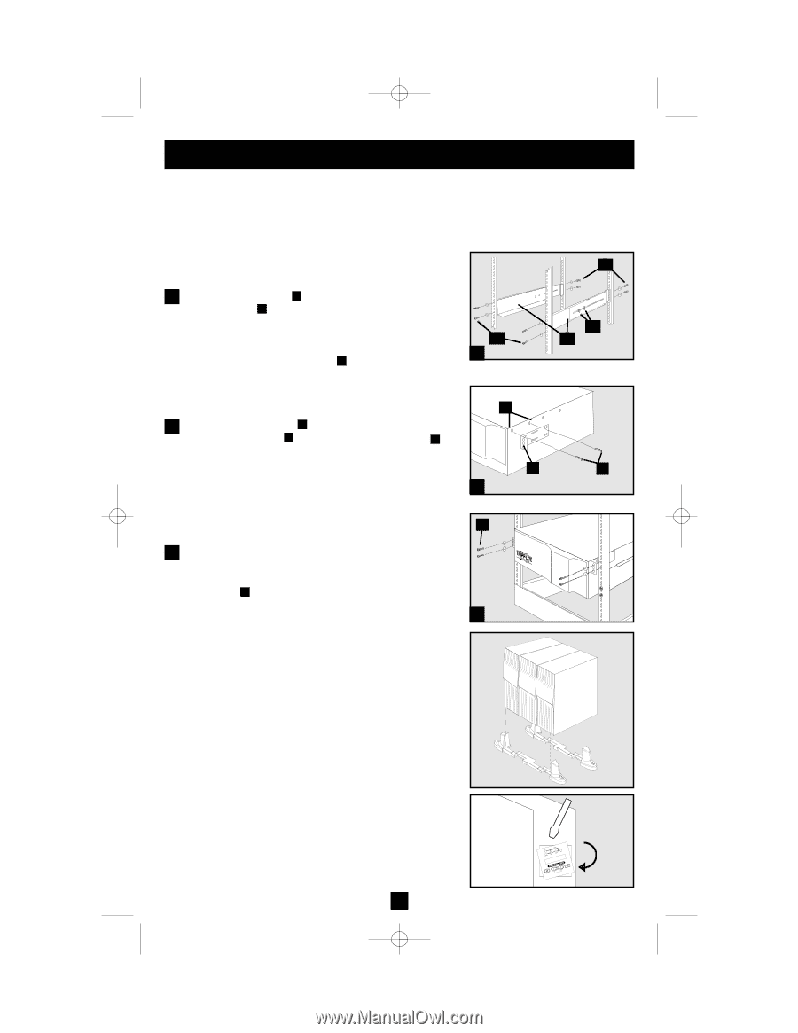
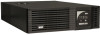
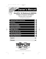
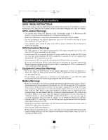
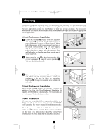
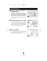
201112103 93-2459.qxd 1/9/2012 12:21 PM Page 3 Mounting Mount your equipment in either a 4-post or 2-post rack or rack enclosure. The user must determine the fitness of hardware and procedures before mounting. If hardware and procedures are not suitable for your application, contact the manufacturer of your rack or rack enclosure. The procedures described in this manual are for common rack and rack enclosure types and may not be appropriate for all applications. 4-Post Rackmount Installation 1 Loosen the wingnuts A on each of the two adjustable side supports B ; adjust the length of the supports to match the depth of your rack; tighten wingnuts. Mount both side supports in the lowest space of your rack on the inside surfaces of the rails with user-supplied #10-32 rack bolts and washers C . Note: Both support ledges should face inward. The side supports' front and back holes are threaded and do not require nuts to secure rack bolts. 2 Attach mounting ears D to the front mounting holes of your equipment E using the screws provided F . The ears should face forward. CC 1 E D 2 C AA BB F G 3 Using an assistant if necessary, lift your equipment and slide it onto the mounting shelves. Attach your equipment to the rack by using the appropriate hardware G through its mounting ears and into the rack rails. 3 2-Post Rackmount Installation If you mount this UPS model in 2-post racks, it requires the addition of a Tripp Lite 2-Post Rackmount Installation Kit (model: 2POSTRMKIT, sold separately). See Installation Kit owner's manual for installation procedure. Tower Installation If you tower mount this UPS, it requires the addition of a Tripp Lite 2U to 9U tower stand (model: 2-9USTAND, sold separately). See owner's manual for installation procedure. Rotate the power module's Control Panel to view it easier while the UPS is tower mounted. Insert a small screwdriver, or other tool, in the slots on either side of the Control Panel. Pop the panel out; rotate it; and pop the panel back into place. 3
-
 1
1 -
 2
2 -
 3
3 -
 4
4 -
 5
5 -
 6
6 -
 7
7 -
 8
8 -
 9
9 -
10
-
11
-
12
-
13
-
14
-
15
-
16
-
17
-
18
-
19
-
20
-
21
-
22
-
23
-
24
-
25
-
26
-
27
-
28
-
29
-
30
-
31
-
32
-
33
-
34
-
35
-
36
 |
 |