Tripp Lite SU5000RT4U Owner's Manual for SU5000RT4U/SU6000RT4U/SU8000RT4U UPS - Page 6
Connection
 |
View all Tripp Lite SU5000RT4U manuals
Add to My Manuals
Save this manual to your list of manuals |
Page 6 highlights
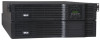
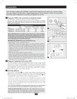
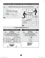
Connection Note: The output voltage is set at 208/120V~ when the UPS is shipped from the factory. If you need to change the output voltage of the UPS, refer to "Output Voltage Selection" in the "Operation" section. You should select the correct output voltage before connecting your equipment to the UPS. 1 Plug your UPS's line cord into an electrical outlet. Your UPS must be connected to a dedicated circuit of sufficient amperage. Note! After you connect the UPS to a live AC power source, the UPS (in "STANDBY MODE") will automatically charge its batteries, but will not supply power to its outlets until it is turned on. Input and Output Ratings Input Maximum Rated Maximum Rated Typical Model Voltage Input Current Output Current Wire Size 1 SU5000RT4U 100-140V (L1-N: L2-N) 20A 30A N/A SU6000RT4U 100-140V (L1-N: L2-N) 24A SU8000RT4U 100-140V (L1-N: L2-N) 34A 30A N/A 40A 8 AWG Model SU8000RT4U has a hardwire input instead of an input cord/plug. Remove the circular knockouts to route the input cabling to the AC input terminal block. Unscrew and remove the utility input terminal block cover to access the AC input terminals. Review the hardwiring cautions below before attempting to connect the UPS input. Hardwiring Cautions (Model SU8000RT4U Only) 2 • Wiring must be done by a qualified electrician. • When making wiring connections, observe the cable connection regulations appropriate to your area [e.g. National Electrical Code (NEC) in the U.S.] at all times. Be sure to install an easily accessible disconnect switch in your installation wiring so you may cut off the AC input of the UPS during fires and other emergencies. Ensure that cables are fitted with cable sleeves and are secured by connector clamps. Tighten connections with a torque of not less than 24-28 inch- B pounds (2.7-3.2 NM). A • Make sure that your equipment is properly grounded. • Using cables of improper size may damage your equipment and cause fire hazards. Choose appropriate cabling and protection circuits to make wiring connections. Ground conductors must be the same size and type as the power conductors used. • Refer to National Electrical Code (NEC) guidelines for proper wire gauge and 3 output protection circuit requirements. 2 Plug your equipment into your UPS. Your UPS is designed to support electronic equipment only. You will overload your UPS if the total VA rating for all the equipment you connect exceeds the UPS's Output Capacity. Do not connect household appliances or laser printers to the UPS's outlets. To find your equipment's VA ratings, look on their nameplates. If the equipment is listed in amps, multiply the number of amps by the input voltage (208V, 240V or 120V) to determine VA. (Example: 1 amp × 120V = 120 VA). 3 Turn the UPS on. Press the UPS's "ON" Button A until you hear a beep to begin inverter operation. Your UPS will now provide output power through its AC outlets to connected equipment. Your UPS will perform a brief self-test and show the results on the LCD Display B . See "Startup Self-Test" in the "Operation" section for the display sequence.* * Cold Start: To use your UPS as a stand-alone power source when AC input power is unavailable (i.e. during a blackout), you can "cold start" your UPS and power connected equipment from the UPS's battery. Your UPS's battery must be at least partially charged for this operation to succeed. Press and hold the "ON" Button until you hear a beep to cold start your UPS. The LCD Display will show ON BATTERY MODE. Battery power will begin discharging. Some electronic equipment may draw more amps during startup; when cold starting, consider reducing the initial load on the UPS. Note: UPS system will function properly upon initial startup; however, maximum runtime for the unit's battery will only be accessible after it has been charged for 24 hours. To Turn the UPS System OFF: Press the UPS's "OFF" Button until you hear a beep. The LCD Display will show "BYPASS MODE." The UPS will continue to automatically charge its batteries as long as AC input power is present. To completely deactivate the UPS, unplug the UPS's line cord when the UPS system is in bypass mode. 6 201102170 932611.indd 6 3/30/2011 10:22:12 AM
-
 1
1 -
 2
2 -
 3
3 -
 4
4 -
 5
5 -
 6
6 -
 7
7 -
 8
8 -
 9
9 -
 10
10 -
 11
11 -
 12
12 -
13
-
14
-
15
-
16
-
17
-
18
-
19
-
20
-
21
-
22
-
23
-
24
-
25
-
26
-
27
-
28
-
29
-
30
-
31
-
32
-
33
-
34
-
35
-
36
-
37
-
38
-
39
-
40
-
41
-
42
-
43
-
44
-
45
-
46
-
47
-
48
-
49
-
50
-
51
-
52
 |
 |
