Tripp Lite SU6000RT4U Owner's Manual for SU5000RT4U/SU6000RT4U/SU8000RT4U UPS - Page 5
Mounting
 |
View all Tripp Lite SU6000RT4U manuals
Add to My Manuals
Save this manual to your list of manuals |
Page 5 highlights
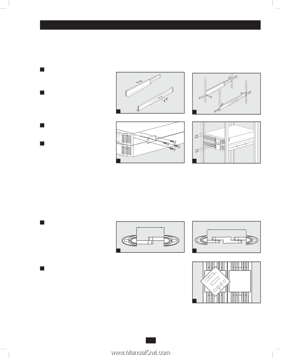
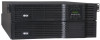
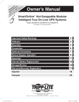
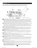
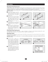
Mounting Mounting (4-Post Rackmount) The UPS includes rackmount rails for 4-post rackmounting. The user must determine the fitness of hardware and procedures before mounting. If hardware and procedures are not suitable for your application, contact the manufacturer of your rack or rack enclosure. The procedures described in this manual are for common rack and rack enclosure types and may not be appropriate for all applications. WARNING! The UPS system is extremely heavy. Use caution when lifting and mounting. User must properly stabilize the UPS when lifting and mounting. 1 Connect the two segments of each shelf using the included attached screws and wing nuts. Leave the screws slightly loose so that the shelves can be adjusted in the next step. 2 Adjust each shelf to fit your rack, then mount them in the lowest available space of your rack with the screws, nuts and washers provided. Note that the support ledges should face inward. 1 2 Tighten the wingnuts that connect the shelf segments. 3 Attach mounting ears to the front mounting holes of your UPS using the screws provided. The ears should face forward. 4 Using one or more assistants, lift your UPS and slide it onto the mounting shelves. Attach your UPS to the rack by passing screws, nuts and washers (user- provided) through its mounting ears and 3 4 into the rack rails. Mounting (2-Post Rackmount) If you mount this UPS model in 2-post racks, it requires the addition of a Tripp Lite 2-Post Rackmount Installation Kit (model: 2POSTRMKITWM, sold separately). See Installation Kit owner's manual for installation procedure. Mounting (Tower) Mount the UPS system in an upright, tower position using 2-9USTAND base stands (optional). The user must determine the fitness of hardware and procedures before mounting. WARNING! The UPS system is extremely heavy. Use caution when lifting and mounting. User must properly stabilize the UPS when lifting and mounting. 1 Adjust the stands to a width of 6.93 inches (176 mm) for a UPS. Adjust the stands to a width of 12.07 inches (306.5 mm) for a UPS and an external battery module. Align the stands approximately 10 inches (254 mm) apart. Have one or more assistants help you place the UPS 1 on its side in the stands. Place the UPS so that its control panel is on top and facing outward. 2 Rotate the UPS's control panel to view it easier while the UPS is tower mounted. Insert a small screwdriver, or other tool, in the slots on either side of the control panel. Pop the panel out; rotate it; and pop the panel back into place. 1 Power Module 1 Power Module 6.93"6(.1973"6(1m76mm) m) 1 Power Module + 1 Power M1odBualett+ery Module 1 Battery Module 12.07" (30162.5.0m7m" )(306.5 mm) 1 BYPASS O/P DC/AC I/P AC/DC BATTERY ON MUTE OFF SELECT SETUP 2 201102170 932611.indd 5 5 3/30/2011 10:22:11 AM
-
 1
1 -
 2
2 -
 3
3 -
 4
4 -
 5
5 -
 6
6 -
 7
7 -
 8
8 -
 9
9 -
 10
10 -
 11
11 -
12
-
13
-
14
-
15
-
16
-
17
-
18
-
19
-
20
-
21
-
22
-
23
-
24
-
25
-
26
-
27
-
28
-
29
-
30
-
31
-
32
-
33
-
34
-
35
-
36
-
37
-
38
-
39
-
40
-
41
-
42
-
43
-
44
-
45
-
46
-
47
-
48
-
49
-
50
-
51
-
52
 |
 |