Troy-Bilt Bronco Operation Manual - Page 20
Seat Adjustment, Parking Brake Adjustment, Adjustments
 |
View all Troy-Bilt Bronco manuals
Add to My Manuals
Save this manual to your list of manuals |
Page 20 highlights
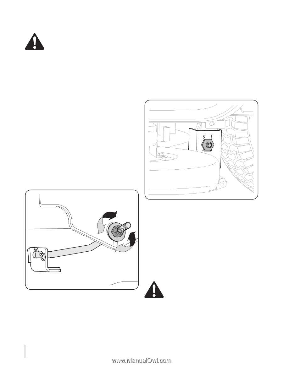
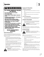
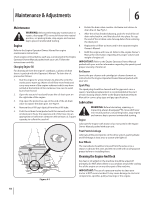
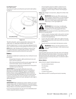
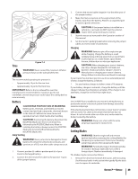
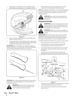
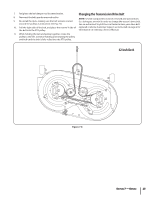
Adjustments WARNING: Never attempt to make any adjustments while the engine is running, except where specified in the operator's manual. Leveling the Deck NOTE: Check the tractor's tire pressure before performing any deck leveling adjustments. Refer to Tires in the Service section of this manual for information regarding tire pressure. Front To Rear The front of the cutting deck is supported by a stabilizer bar that can be adjusted to level the deck from front to rear. The front of the deck should be between ¼-inch and 3⁄8-inch lower than the rear of the deck. Adjust if necessary as follows: 1. With the tractor parked on a firm, level surface, place the lever for lifting the platform on the second to the top notch (second highest position) and rotate the blade as close to the discharge channel that is parallel to the tractor. 2. Measure the distance from the front of the blade tip to the ground and the rear of the blade tip to the ground. The first measurement taken should be between ¼" and 3⁄8" less than the second measurement. Determine the approximate distance necessary for proper adjustment and proceed, if necessary, to the next step. 3. Locate the jam nut and lock nut on the front side of the stabilizer bracket. See Fig. 6-3. After loosening the jam nut: • Tighten the lock nut to raise the front of the deck; • Loosen the lock nut to lower the front of the deck. Side to Side If the cutting deck appears to be mowing unevenly, a side to side adjustment can be performed. Adjust if necessary as follows: 1. With the tractor parked on a firm, level surface, place the deck lift lever in the second from the top notch (second highest position) and rotate both blades so that they are perpendicular with the tractor. 2. Measure the distance from the outside of the left blade tip to the ground and the distance from the outside of the right blade tip to the ground. Both measurements taken should be equal. If they're not, proceed to the next step. 3. Loosen, but do NOT remove, the hex cap screw on the left deck hanger bracket. See Fig. 6-4. Figure 6-3 4. Retighten the jam nut loosened earlier when proper adjustment is achieved. Figure 6-4 4. Balance the deck by using a wrench to turn the adjustment gear (found immediately behind the hex cap screw just loosened) clockwise/up or counterclockwise/down. The deck is properly balanced when both blade tip measurements taken earlier are equal. 5. Retighten the hex cap screw on the left deck hanger bracket when proper adjustment is achieved. Seat Adjustment Refer to the Set-Up and Assembly section of this manual for seat adjustment instructions. Parking Brake Adjustment WARNING: Never attempt to adjust the brakes while the engine is running. Always disengage PTO, move shift lever into neutral position, stop engine and remove key to prevent unintended starting. If the tractor does not come to a complete stop when the brake pedal is completely depressed, or if the tractor's rear wheels can roll with the parking brake applied, the brake is in need of adjustment. See an authorized Troybilt Service Dealer to have your brakes properly adjusted. 20 Section 6- Maintenance & Adjustments
-
 1
1 -
2
-
3
-
4
-
5
-
6
-
7
-
8
-
9
-
10
-
11
-
12
-
13
-
14
-
 15
15 -
 16
16 -
 17
17 -
 18
18 -
 19
19 -
 20
20 -
 21
21 -
 22
22 -
 23
23 -
 24
24 -
 25
25 -
26
-
27
-
28
-
29
-
30
-
31
-
32
-
33
-
34
-
35
-
36
-
37
-
38
-
39
-
40
-
41
-
42
-
43
-
44
-
45
-
46
-
47
-
48
-
49
-
50
-
51
-
52
-
53
-
54
-
55
-
56
-
57
-
58
-
59
-
60
-
61
-
62
-
63
-
64
 |
 |