Troy-Bilt TB380 Operation Manual - Page 12
Set-Up
 |
View all Troy-Bilt TB380 manuals
Add to My Manuals
Save this manual to your list of manuals |
Page 12 highlights
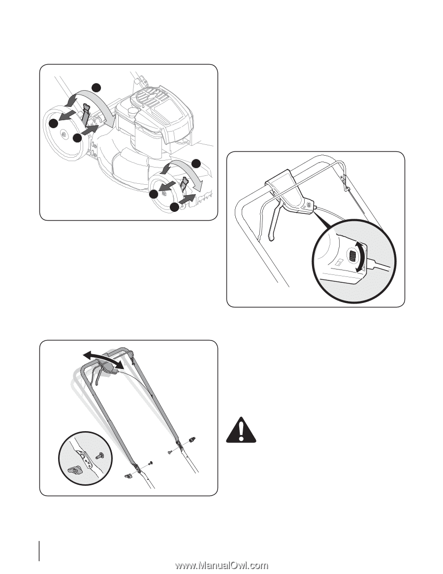
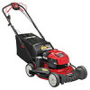
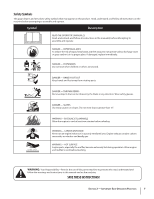
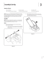
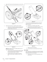
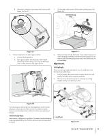
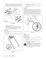
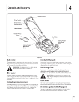
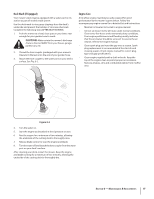
NOTE: For mowers with low wheels, the height adjustment levers move in the opposite direction to adjust; for those with high wheels, the levers move in the same direction. 2 Higher 1 Lower 3 2. Position the handle in one of the three positions that is most comfortable. See Fig. 3-11 inset. 3. Secure into position with wing nuts and carriage bolts removed earlier. Drive Control The adjustment wheel is located in the drive control handle housing and is used to tighten or loosen the drive belt. You will need to adjust the drive control if the mower does not propel itself with the drive control engaged or if the mower's wheels hesitate with the drive control engaged. If either of these conditions occur, rotate adjustment wheel clockwise to tighten cable or counterclockwise to loosen the cable. See Fig. 3-12. Higher 2 High Wheel 1 3 Lower Figure 3-10A 3. Release lever towards deck. IMPORTANT: Both the front and rear wheels must be placed in the same relative position. For rough or uneven lawns, move the height adjustment levers to a higher position. This will stop scalping of grass. Handle Pitch For convenience of operation, you may adjust the pitch of the handle as follows: 1. Remove wing nuts and carriage bolts from handle. See Fig. 3-11. Tighten Loosen Figure 3-12 Set-Up Gas and Oil Fill-Up Refer to the separate engine owner's manual for additional engine information. 1. Add oil provided before starting unit for the first time out of the box. 2. Service the engine with gasoline as instructed in the separate engine owner's manual. WARNING: Use extreme care when handling gasoline. Gasoline is extremely flammable and the vapors are explosive. Never fuel the machine indoors or while the engine is hot or running. Extinguish cigarettes, cigars, pipes and other sources of ignition. Figure 3-11 12 Section 3 - Assembly & Set-Up
-
 1
1 -
2
-
3
-
4
-
5
-
6
-
 7
7 -
 8
8 -
 9
9 -
 10
10 -
 11
11 -
 12
12 -
 13
13 -
 14
14 -
 15
15 -
 16
16 -
 17
17 -
18
-
19
-
20
-
21
-
22
-
23
-
24
-
25
-
26
-
27
-
28
-
29
-
30
-
31
-
32
-
33
-
34
-
35
-
36
-
37
-
38
-
39
-
40
-
41
-
42
-
43
-
44
-
45
-
46
-
47
-
48
-
49
-
50
-
51
-
52
 |
 |