URC MRF-250 Owners Manual - Page 7
self-adhesive
 |
View all URC MRF-250 manuals
Add to My Manuals
Save this manual to your list of manuals |
Page 7 highlights
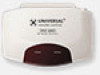
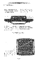
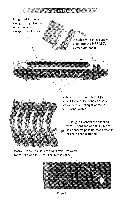
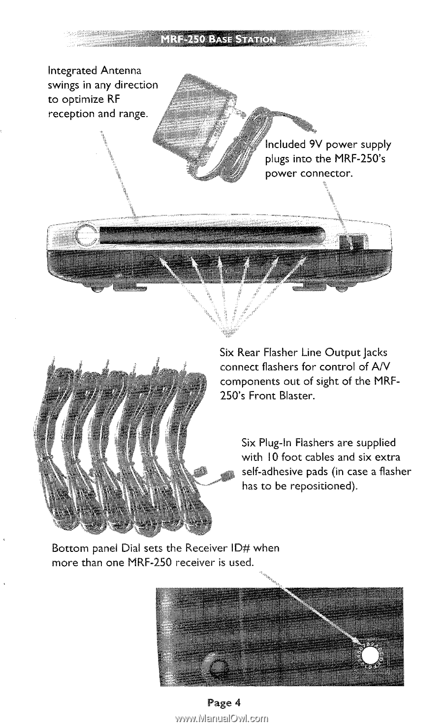
I, I MRF-250 BASE STATION gen Integrated Antenna swings in any direction to optimize RF reception and range. Included 9V power supply plugs into the MRF-250's power connector. Six Rear Flasher Line Output Jacks connect flashers for control of A/V components out of sight of the MRF250's Front Blaster. Six Plug-In Flashers are supplied with 10 foot cables and six extra self-adhesive pads (in case a flasher has to be repositioned). Bottom panel Dial sets the Receiver ID# when more than one MRF-250 receiver is used. Page 4
-
 1
1 -
 2
2 -
 3
3 -
 4
4 -
 5
5 -
 6
6 -
 7
7 -
 8
8 -
 9
9 -
 10
10 -
 11
11 -
 12
12 -
13
-
14
-
15
-
16
 |
 |
I,
I
MRF-250
BASE
STATION
ge
n
Integrated
Antenna
swings
in
any
direction
to
optimize
RF
reception
and
range.
Included
9V
power
supply
plugs
into
the
MRF-250's
power
connector.
Six
Rear
Flasher
Line
Output
Jacks
connect
fl
ashers
for
control
of
A/V
components
out
of
sight
of
the
MRF-
250's
Front
Blaster.
Six
Plug
-In
Flashers
are
supplied
with
10
foot
cables
and
six
extra
self-adhesive
pads
(in
case
a
fl
asher
has
to
be
repositioned).
Bottom
panel
Dial
sets
the
Receiver
ID#
when
more
than
one
MRF-250
receiver
is
used.
Page
4