URC MRF-350 Owners Manual - Page 6
Optimizing Range and Reliability - rfs
 |
View all URC MRF-350 manuals
Add to My Manuals
Save this manual to your list of manuals |
Page 6 highlights
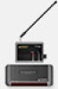
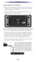
MRF-350 BASE STATION Optimizing Range and Reliability 1. Power on all AV components, lower all dimmers to 50% and power on anything that may create RF Interference (particularly devices with high speed microprocessors or hard drives). 2. Check that the address wheel on the bottom of the MRF-350 is set to ID#0 (the interference "sniffing" position). Slide off the mounting plate to reveal the RF ID# rotary switch. Check that the arrow pointer in the center of the wheel is pointed to 0, the default "interence sniffing" position. If it is not, use a small flat blade screwdriver (included) to set the RF ID# to 0. 3. Connect the MRF-350 to its DC wall adapter and plug the wall adapter into a live AC outlet. Place the MRF-350 in a convenient central location in the equipment rack. Unlike an MRF-250, the MRF-350 can be placed next to components with hard drives or high speed microprocessors. There is no RF circuitry inside the MRF-350 itself. 4. Connect the RFX-250 to the MRF-350's RF INPUT. You can connect to either the screw connector or the jack as shown: When connecting a single RFX-250 to the MRF-350 utilize the cable with 3.5 mm plugs on both ends. When you need a longer wire or are connecting up to three RFX-250s, use a cable with tinned ends. Cable can be extended as much as 200', then connected to the removable screw connector plugs. If you use CAT 5 connect four conductors to GND (one from each twisted pair) and connect the remaining conductors two at a time to 5V and DATA . Page 3
-
 1
1 -
 2
2 -
 3
3 -
 4
4 -
 5
5 -
 6
6 -
 7
7 -
 8
8 -
 9
9 -
 10
10 -
 11
11 -
 12
12 -
13
-
14
-
15
-
16
-
17
-
18
-
19
-
20
 |
 |
