Uniden UM525 English Owners Manual - Page 14

Choosing a Location, Engine Noise Suppression, Installing the Radio - problems

Page 14 highlights

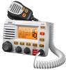
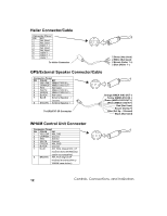
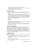
• All connections are "plug-in" type for easy removal of the radio. • By using an optional WHAM or WHAM x 4 (Wireless Handheld Access Microphone), the UM-525 can be mounted completely out of the way. • Also optionally available is a flush mount bracket (FMB321). Choosing a Location Here are some important factors to consider in selecting the location for your UM-525. • The UM-525 is completely waterproof, but will last longer if protected from spray and splash. • Keep the battery leads as short as possible. Direct connection to the battery is most desirable. If direct connection can not be made with the supplied power lead, any extension should be made with #12-14 AWG wire. Long extensions should use larger gauge wire. • Keep the antenna lead-in wire as short as possible. If you must use a long lead-in wire as in the case of a sailboat masthead antenna installation, we recommend you upgrade your lead-in wire according to the following table: RG-58

  • 1
  • 2
  • 3
  • 4
  • 5
  • 6
  • 7
  • 8
  • 9
  • 10
  • 11
  • 12
  • 13
  • 14
  • 15
  • 16
  • 17
  • 18
  • 19
  • 20
  • 21
  • 22
  • 23
  • 24
  • 25
  • 26
  • 27
  • 28
  • 29
  • 30
  • 31
  • 32
  • 33
  • 34
  • 35
  • 36
  • 37
  • 38
  • 39
  • 40
  • 41
  • 42
  • 43
  • 44
  • 45
  • 46
  • 47
  • 48
  • 49
  • 50
  • 51
  • 52
  • 53
  • 54
  • 55
  • 56
  • 57
  • 58
  • 59
  • 60
  • 61
  • 62
  • 63
  • 64
  • 65
  • 66
  • 67
  • 68
  • 69
  • 70
  • 71
  • 72
  • 73
  • 74
  • 75
  • 76
  • 77
  • 78
  • 79
  • 80
  • 81
  • 82
  • 83
  • 84
  • 85
  • 86
  • 87
  • 88
  • 89
  • 90
  • 91
  • 92
  • 93
  • 94
  • 95
  • 96
  • 97
  • 98
  • 99
  • 100
  • 101
  • 102
  • 103
  • 104
  • 105
  • 106
  • 107
  • 108
  • 109
  • 110
  • 111
  • 112
  • 113
  • 114
  • 115
  • 116
  • 117
  • 118
  • 119
  • 120
  • 121
  • 122
  • 123
  • 124
  • 125
  • 126
  • 127
  • 128
  • 129
  • 130
  • 131
  • 132
  • 133
  • 134
  • 135
  • 136
  • 137
  • 138
  • 139
  • 140
  • 141
  • 142
  • 143
  • 144
  • 145
  • 146
  • 147
  • 148
  • 149
  • 150
  • 151
  • 152
  • 153
  • 154
  • 155
  • 156
  • 157

Setting Up The Radio
14
All connections are “plug-in” type for easy removal of the radio.
By using an optional WHAM or WHAM x 4 (Wireless Handheld Access Microphone), the
UM-525 can be mounted completely out of the way.
Also optionally available is a flush mount bracket (FMB321).
Choosing a Location
Here are some important factors to consider in selecting the location for your UM-525.
The UM-525 is completely waterproof, but will last longer if protected from spray and
splash.
Keep the battery leads as short as possible. Direct connection to the battery is most
desirable. If direct connection can not be made with the supplied power lead, any extension
should be made with #12-14 AWG wire. Long extensions should use larger gauge wire.
Keep the antenna lead-in wire as short as possible. If you must use a long lead-in wire as in
the case of a sailboat masthead antenna installation, we recommend you upgrade your
lead-in wire according to the following table:
RG-58 <20'
RG-8X <35'
RG-8U <60'
Locate your antenna as high as possible and clear from metal objects. The reliable range of
coverage is a direct function of the antenna height.
Select a location that allows free air flow around the heat sink on the rear of the radio.
Select a location well away from the ship's compass. Auxiliary speakers also should be
located away from the compass.
Engine Noise Suppression
Interference from the noise generated by the electrical systems of engines is sometimes a
problem with radios. The UM-525 has been designed to be essentially impervious to ignition
noise and alternator noise. However, in some installations it may be necessary to take
measures to further reduce the effect of noise interference. The UM-525 radio DC battery
wires, antenna lead, and accessory cables should be routed away from the engine and engine
compartment, and from power cabling carrying high currents. In severe cases of noise
interference, it may be necessary to install a noise suppression kit. Contact the dealer where
you purchased the radio for more information.
Installing the Radio
After you have carefully considered the various factors affecting your choice of location, follow
these steps to install the radio.
1.
Position the radio (with the bracket, microphone, power cord, antenna and any auxiliary
cables installed) into the selected location to assure there is no interference with the
surrounding items.
2.
Mark the location of the mounting bracket.
3.
Remove the bracket from the radio and use it as a template to mark the holes to be drilled
for the mounting hardware.