Via EPIA-M10000G User Manual - Page 27
Fast IrDA Infrared Module Connector: IR, Consumer Infrared Module, PS2 Header: CIR / EXT_KBMS
 |
View all Via EPIA-M10000G manuals
Add to My Manuals
Save this manual to your list of manuals |
Page 27 highlights
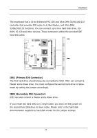
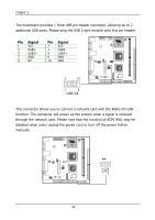
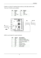
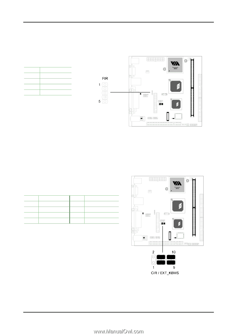
Installation Fast IrDA Infrared Module Connector: IR This connector allows you to connect an IrDA Infrared module. You must configure the setting through the BIOS setup to activate the IR function. Pin Signal 1 VCC 2 IRRX1 3 IRRX 4 GND 5 IRTX Consumer Infrared Module, PS2 Header: CIR / EXT_KBMS When the leader is not in use, please short pin 3&5, pin 4&6, pin 7&9, and pin 8&10. Pin Signal Pin Signal 1 +5V 2 GND 3 KB_CLK 4 KB_DATA 5 EXT_KBCLK 6 EXT_KBDATA 7 MS_CLK 8 MS_DATA 9 EXT_MSCLK 10 EXT_MSDATA 19
-
 1
1 -
2
-
3
-
4
-
5
-
6
-
7
-
8
-
9
-
10
-
11
-
12
-
13
-
14
-
15
-
16
-
17
-
18
-
19
-
20
-
21
-
 22
22 -
 23
23 -
 24
24 -
 25
25 -
 26
26 -
 27
27 -
 28
28 -
 29
29 -
 30
30 -
 31
31 -
 32
32 -
33
-
34
-
35
-
36
-
37
-
38
-
39
-
40
-
41
-
42
-
43
-
44
-
45
-
46
-
47
-
48
-
49
-
50
-
51
-
52
-
53
-
54
-
55
-
56
-
57
-
58
-
59
-
60
-
61
-
62
-
63
-
64
-
65
-
66
-
67
-
68
-
69
-
70
-
71
-
72
-
73
-
74
-
75
-
76
-
77
-
78
-
79
-
80
 |
 |
Installation
19
Fast IrDA Infrared Module Connector: IR
This connector allows you to connect an IrDA Infrared module. You must
configure the setting through the BIOS setup to activate the IR function.
Pin
Signal
1
VCC
2
IRRX1
3
IRRX
4
GND
5
IRTX
Consumer Infrared Module,
PS2 Header: CIR / EXT_KBMS
When the leader is not in use, please short pin 3&5, pin 4&6, pin 7&9, and
pin 8&10.
Pin
Signal
Pin
Signal
1
+5V
2
GND
3
KB_CLK
4
KB_DATA
5
EXT_KBCLK
6
EXT_KBDATA
7
MS_CLK
8
MS_DATA
9
EXT_MSCLK
10
EXT_MSDATA