Via EX10000EG User Manual - Page 21
ATX 20-Pin Power Connector
 |
UPC - 825529003789
View all Via EX10000EG manuals
Add to My Manuals
Save this manual to your list of manuals |
Page 21 highlights
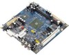
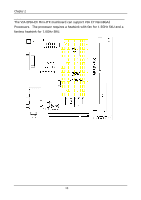
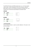
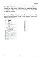
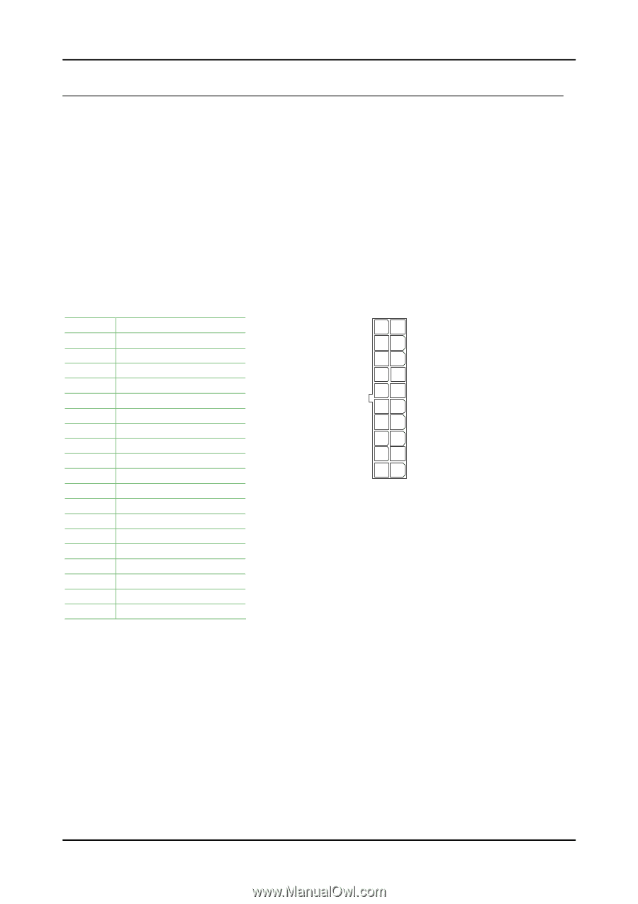
Installation CONNECTING THE POWER SUPPLY The VIA EPIA-EX Mini-ITX mainboard supports a conventional ATX power supply for the power system. Before inserting the power supply connector, always make sure that all components are installed correctly to ensure that no damage will be caused. ATX 20-Pin Power Connector To connect the ATX power supply, make sure the power plug is inserted in the proper orientation and the pins are aligned. Then push down the plug firmly into the connector. Pin Signal 1 +3.3V 2 +3.3V 3 GND 4 +5V 5 GND 6 +5V 7 GND 8 Power Good 9 +5V Standby 10 +12V 11 +3.3V 12 -12V 13 GND 14 Power Supply On 15 GND 16 GND 17 GND 18 -5V 19 +5V 20 +5V ATXPWR 11 1 20 10 13
-
 1
1 -
2
-
3
-
4
-
5
-
6
-
7
-
8
-
9
-
10
-
11
-
12
-
13
-
14
-
15
-
 16
16 -
 17
17 -
 18
18 -
 19
19 -
 20
20 -
 21
21 -
 22
22 -
 23
23 -
 24
24 -
 25
25 -
 26
26 -
27
-
28
-
29
-
30
-
31
-
32
-
33
-
34
-
35
-
36
-
37
-
38
-
39
-
40
-
41
-
42
-
43
-
44
-
45
-
46
-
47
-
48
-
49
-
50
-
51
-
52
-
53
-
54
-
55
-
56
-
57
-
58
-
59
-
60
-
61
-
62
-
63
-
64
-
65
-
66
-
67
-
68
-
69
-
70
-
71
-
72
-
73
-
74
-
75
-
76
-
77
-
78
-
79
-
80
 |
 |
Installation
13
C
ONNECTING THE
P
OWER
S
UPPLY
The VIA EPIA-EX Mini-ITX mainboard supports a conventional ATX power
supply for the power system.
Before inserting the power supply connector,
always make sure that all components are installed correctly to ensure that
no damage will be caused.
ATX 20-Pin Power Connector
To connect the ATX power supply, make sure the power plug is inserted in
the proper orientation and the pins are aligned.
Then push down the plug
firmly into the connector.
Pin
Signal
1
+3.3V
2
+3.3V
3
GND
4
+5V
5
GND
6
+5V
7
GND
8
Power Good
9
+5V Standby
10
+12V
11
+3.3V
12
-12V
13
GND
14
Power Supply On
15
GND
16
GND
17
GND
18
-5V
19
+5V
20
+5V
ATXPWR
1
10
11
20