Via EX10000EG User Manual - Page 26
Front Panel Audio Connector, F_AUDIO, KBMS Connector, KBMS1
 |
UPC - 825529003789
View all Via EX10000EG manuals
Add to My Manuals
Save this manual to your list of manuals |
Page 26 highlights
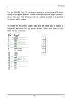
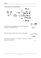
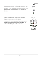
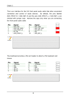
Chapter 2 Front Panel Audio Connector: F_AUDIO This is an interface for the VIA front panel audio cable that allow convenient connection and control of audio devices. By default, the pins labeled AUD_FPOUT_R / AUD_RET_R and the pins AUD_FPOUT_L / AUD_RET_L are shorted with jumper caps. Remove the caps only when you are connecting the front panel audio cable. F_AUDIO1 Pin Signal 1 AUD_MIC 3 AUD_MIC_BIAS 5 AUD_FPOUT_R 7 HP_ON 9 AUD_FPOUT_L Pin Signal 2 AUD_GND 4 AUD_FNT_DET 6 AUD_RET_R 8 Key 10 AUD_RET_L 1 2 9 10 Note: If you don't want to connect to the front audio header, pins 5 & 6, 9 & 10 have to be jumpered in order to have signal output directed to the rear audio ports. Otherwise, the Line-Out connector on the back panel will not function. KBMS Connector: KBMS1 The mainboard provides a PS2 pin header to attach a PS2 keyboard and mouse. Pin Signal 1 +5VDUAL 3 Key 5 GND 7 KB_DT 9 KB_CK Pin Signal 2 +5VDUAL 4 Key 6 GND 8 MS_DT 10 MS_CK KBMS1 1 2 9 10 Note: When the pin header is not in use, please short pin 3&5, pin 4&6, pin 7&9 and pin 8&10. 18
-
 1
1 -
2
-
3
-
4
-
5
-
6
-
7
-
8
-
9
-
10
-
11
-
12
-
13
-
14
-
15
-
16
-
17
-
18
-
19
-
20
-
 21
21 -
 22
22 -
 23
23 -
 24
24 -
 25
25 -
 26
26 -
 27
27 -
 28
28 -
 29
29 -
 30
30 -
 31
31 -
32
-
33
-
34
-
35
-
36
-
37
-
38
-
39
-
40
-
41
-
42
-
43
-
44
-
45
-
46
-
47
-
48
-
49
-
50
-
51
-
52
-
53
-
54
-
55
-
56
-
57
-
58
-
59
-
60
-
61
-
62
-
63
-
64
-
65
-
66
-
67
-
68
-
69
-
70
-
71
-
72
-
73
-
74
-
75
-
76
-
77
-
78
-
79
-
80
 |
 |
