ViewSonic PJ501 User Guide - Page 10
Cabling, Power Connection - manual
 |
UPC - 766907692815
View all ViewSonic PJ501 manuals
Add to My Manuals
Save this manual to your list of manuals |
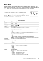
Page 10 highlights
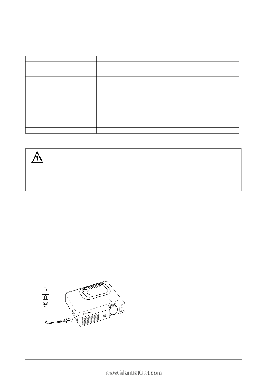
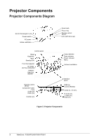
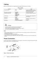
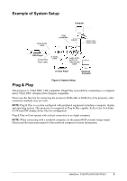
Cabling Refer to the table below for connecting each terminal of the projector to a device. Function Analog RGB input RS-232C communication Component video input S-video input Video input/ Audio input Audio Input RGB Table 2: Cabling Terminal CONTROL VIDEO Y VIDEO CB/PB VIDEO CR/PR S-VIDEO VIDEO AUDIO (L) AUDIO (R) 3.5 mm to mini-jack L/R Cable Accessory RGB cable or optional RGB cable with D-sub 15-pin shrink jack and inch thread screws Optional RS-232C cable Accessory component video cable Accessory S-video cable with mini DIN 4-pin jack Accessory video/audio cable with RCA jacks Optional Warnings • Incorrect connections could result in fire or electrical shock. • Before connecting, turn off all devices to be connected. • Use the cables that are packaged with the product. Refer to page 27. • See "Power Cord Safety Guidelines" on page 28. NOTE: • Before connecting, read the instruction manuals of the devices to be connected, and make sure that the projector is compatible with the device(s). • Securely tighten the screws on the connectors. • For some RGB input modes, the optional Mac adapter is necessary. • Some computers may have multiple display screen modes. You may not be able to use some of the modes with this projector. Power Connection Use the correct power cord supplied with your projector. Connect the AC inlet of the projector to the power outlet as shown in the graphic below. Figure 7: Power Cord Connect 7 ViewSonic PJ500/PJ550/PJ501/PJ551
-
 1
1 -
2
-
3
-
4
-
 5
5 -
 6
6 -
 7
7 -
 8
8 -
 9
9 -
 10
10 -
 11
11 -
 12
12 -
 13
13 -
 14
14 -
 15
15 -
16
-
17
-
18
-
19
-
20
-
21
-
22
-
23
-
24
-
25
-
26
-
27
-
28
-
29
-
30
-
31
-
32
 |
 |