ViewSonic PJD5555W PJD5153 User Guide English - Page 13
Projector exterior view - remote
 |
View all ViewSonic PJD5555W manuals
Add to My Manuals
Save this manual to your list of manuals |
Page 13 highlights
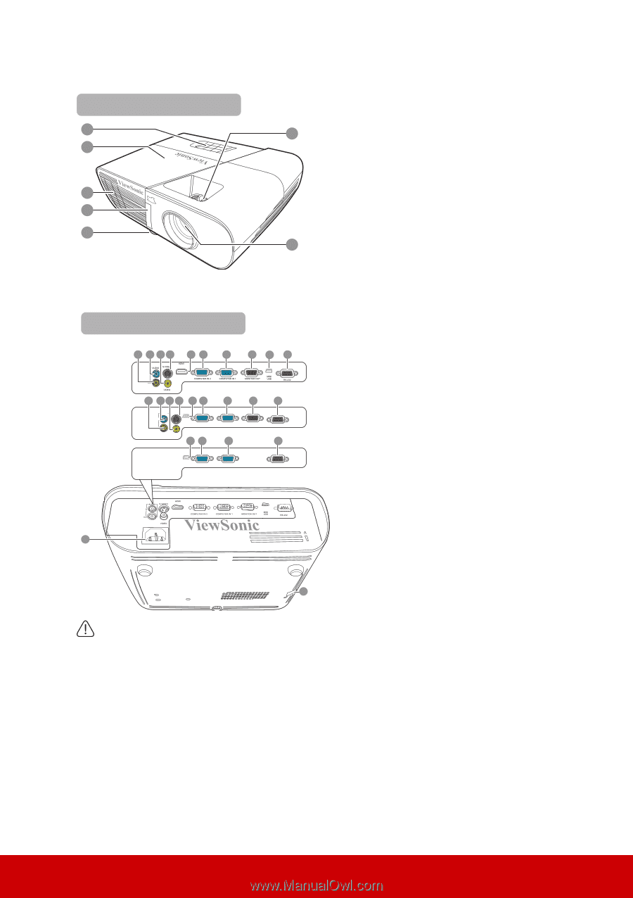
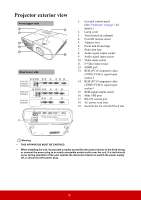
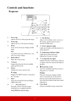
Projector exterior view Front/upper side 1 6 2 3 4 5 7 Rear/lower side 8 9 10 11 12 13 14 PJD5155/ PJD5255/ PJD5555w 15 16 17 PJD5153/ PJD5253 PJD5151/ PJD5250 8 9 10 11 16 13 AUDIO S-VIDEO IN MINI USB OUT COMPUTER IN 2 VIDEO 16 13 14 COMPUTER IN 1 14 15 MONITOR OUT 17 RS-232 17 MINI USB COMPUTER IN 2 COMPUTER IN 1 RS-232 1. External control panel (See "Projector" on page 7 for details.) 2. Lamp cover 3. Vent (heated air exhaust) 4. Front IR remote sensor 5. Adjuster foot 6. Focus and Zoom rings 7. Projection lens 8. Audio signal output socket 9. Audio signal input socket 10. Video input socket 11. S-Video input socket 12. HDMI port 13. RGB (PC)/Component video (YPbPr/YCbCr) signal input socket-2 14. RGB (PC)/Component video (YPbPr/YCbCr) signal input socket-1 15. RGB signal output socket 16. Mini USB port 17. RS-232 control port 18. AC power cord inlet 19. Security bar for anti-theft lock slot 18 19 Warning • THIS APPARATUS MUST BE EARTHED. • When installing the unit, incorporate a readily accessible disconnect device in the fixed wiring, or connect the power plug to an easily accessible socket-outlet near the unit. If a fault should occur during operation of the unit, operate the disconnect device to switch the power supply off, or disconnect the power plug. 6
-
 1
1 -
2
-
3
-
4
-
5
-
6
-
7
-
 8
8 -
 9
9 -
 10
10 -
 11
11 -
 12
12 -
 13
13 -
 14
14 -
 15
15 -
 16
16 -
 17
17 -
 18
18 -
19
-
20
-
21
-
22
-
23
-
24
-
25
-
26
-
27
-
28
-
29
-
30
-
31
-
32
-
33
-
34
-
35
-
36
-
37
-
38
-
39
-
40
-
41
-
42
-
43
-
44
-
45
-
46
-
47
-
48
-
49
-
50
-
51
-
52
-
53
-
54
-
55
-
56
-
57
-
58
-
59
-
60
-
61
-
62
-
63
-
64
-
65
-
66
-
67
-
68
-
69
-
70
-
71
-
72
-
73
-
74
-
75
-
76
-
77
-
78
-
79
-
80
-
81
-
82
-
83
-
84
-
85
 |
 |