ViewSonic VG2756a-2K User Guide English - Page 5
W x H, Interface Pad, W x H x D, Pad Hole, Screw
 |
View all ViewSonic VG2756a-2K manuals
Add to My Manuals
Save this manual to your list of manuals |
Page 5 highlights
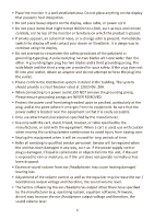
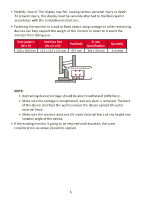
• Stability Hazard: The display may fall, causing serious personal injury or death. To prevent injury, this display must be securely attached to the floor/wall in accordance with the installation instructions. • Fastening the monitor to a wall or fixed object using cordage or other restraining devices can help support the weight of the monitor in order to prevent the monitor from falling over. Hole pattern (W x H) 100 x 100 mm Interface Pad (W x H x D) 115 x 115 x 2.6 mm Pad Hole Ø 5 mm Screw Specification M4 x 10 mm Quantity 4 screws or VESA wall mounƟng hole NOTE: • Restraining device/cordage should be able to withstand 100N force. • Make sure the cordage is straightened, and any slack is removed. The back of the device shall face the wall to ensure the device cannot tilt under external force. • Make sure the monitor does not tilt under external force at any height and rotation angle of the device. • If the existing monitor is going to be retained and relocated, the same considerations as above should be applied. 5
-
 1
1 -
 2
2 -
 3
3 -
 4
4 -
 5
5 -
 6
6 -
 7
7 -
 8
8 -
 9
9 -
 10
10 -
 11
11 -
12
-
13
-
14
-
15
-
16
-
17
-
18
-
19
-
20
-
21
-
22
-
23
-
24
-
25
-
26
-
27
-
28
-
29
-
30
-
31
-
32
-
33
-
34
-
35
-
36
-
37
-
38
-
39
-
40
-
41
-
42
-
43
-
44
-
45
-
46
-
47
-
48
-
49
-
50
-
51
-
52
-
53
-
54
-
55
-
56
-
57
-
58
-
59
-
60
-
61
-
62
-
63
-
64
-
65
-
66
-
67
-
68
-
69
-
70
-
71
 |
 |
