ViewSonic VX800-3 Service Manual - Page 41
Audio Board
 |
UPC - 766907812718
View all ViewSonic VX800-3 manuals
Add to My Manuals
Save this manual to your list of manuals |
Page 41 highlights
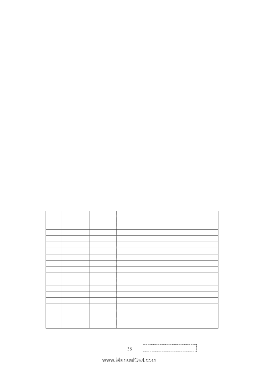
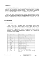
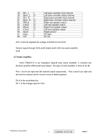
1.5 DDC 1/2 B IC600 (24LC02) & IC602 (24LC21A) can continuously transmit its extended identification, "EDID" using DDC1 communication channel. In addition, the monitor can respond to a request for EDID, or complete VDIF, to be transmitted using DDC2, level B commands. Pin6 SCL is clock input for DDC 2B, pin5 SDA for data input, and pin7 VCLK is clock input for DDC1. In DDC1 data transfer (UNI-directional mode), the VCLK input pin is used as an input clock for data transmission and SDA output pin is used as serial data line the SCL pin will hold high. The DDC2B node (BI-directional mode) BUS consists of two wires. SCL is for the data transmission clock and SDA is for the data line. 3.2 Audio Board 2.1 Audio processor ICA2 (PT2313L) is a four-channel digital audio processor utilizing CMOS Technology .Volume, Bass, Treble, Balance, Front/Rear Fader Processor are incorporated into a single chip. Loudness function and Selectable input gain are also provided to build a highly effective electronic Audio processor having the highest performance and reliability with the least external components. And all functions are programmable using the IIC BUS PIN# 1 2 3 4 5 6 7 8 9 10 11 12 13 14 15 16 17 PIN NAME I/O REF - VDD - Agnd - Treb_L I Treb_R I RIN I Rout O Loud_R I Rin 3 I Rin 2 I Rin 1 I Loud_L I Lin 3 I Lin 2 I Lin 1 I LIN I Lout O DESCRIPTION Analog reference voltage(1/2 VDD) Supply input voltage Analog ground Left channel input for treble control Right channel input for treble control Audio processor right channel input Gain output&input selector for right channel Right channel loudness input Right channel input 3 Right channel input 2 Right channel input 1 Left channel loudness input Light channel input 3 Light channel input 2 Light channel input 1 Audio processor left channel input Gain output and input selector for left channel ViewSonic Corporation 47! Confidential - Do Not Copy VX800-3
-
 1
1 -
2
-
3
-
4
-
5
-
6
-
7
-
8
-
9
-
10
-
11
-
12
-
13
-
14
-
15
-
16
-
17
-
18
-
19
-
20
-
21
-
22
-
23
-
24
-
25
-
26
-
27
-
28
-
29
-
30
-
31
-
32
-
33
-
34
-
35
-
 36
36 -
 37
37 -
 38
38 -
 39
39 -
 40
40 -
 41
41 -
 42
42 -
 43
43 -
 44
44 -
 45
45 -
 46
46 -
47
-
48
-
49
-
50
-
51
-
52
-
53
-
54
-
55
-
56
-
57
-
58
-
59
-
60
-
61
-
62
-
63
-
64
-
65
-
66
-
67
-
68
-
69
-
70
-
71
-
72
-
73
-
74
-
75
-
76
-
77
-
78
-
79
-
80
-
81
-
82
-
83
-
84
-
85
 |
 |