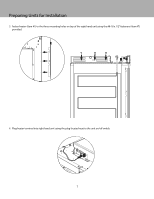
Viking 24" Fully Integrated All Freezer with 5/7 Series Panel Multi-Unit Refri - Page 9
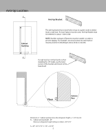
Lift Pattern Diagram, FRONT
 |
View all Viking 24" Fully Integrated All Freezer with 5/7 Series Panel manuals
Add to My Manuals
Save this manual to your list of manuals |
Page 9 highlights
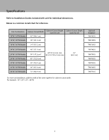
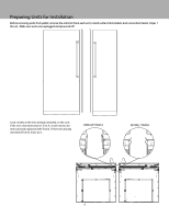
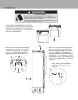
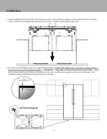
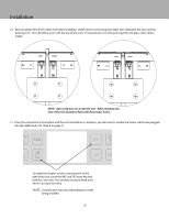
Installation 8. If unit leveling feet were used, lower units back onto rollers. Plug in electrical supply and roll connected units into cabinet cutout. Units must be plugged into separate electric outlets. Connect water supply to each unit. 9. Lift units to desired height using 5/16" socket and hand ratchet. DO NOT USE A DRILL-(refer to lift pattern diagram below to ensure that units are gradually lifted together.) **IMPORTANT** - Only make 4 turns at a time with the hand ratchet**. Attach units to cabinet side trim and fasteners included with the units. Install stainless magnetic side trim once fastened. (Use installation guide included with individual units as a reference.) .125" WHEN INSTALLED Lift Pattern Diagram 2 REAR 6 4 REAR 8 7 FRONT 3 5 FRONT 1 9
-
 1
1 -
2
-
3
-
 4
4 -
 5
5 -
 6
6 -
 7
7 -
 8
8 -
 9
9 -
 10
10 -
 11
11 -
 12
12 -
 13
13 -
 14
14 -
15
-
16
-
17
-
18
-
19
-
20
-
21
-
22
-
23
-
24
 |
 |
