Viking BVGRC8366BWSS Installation Instructions - Page 6
Electrical & Gas Requirements, Clearance Dimensions
 |
View all Viking BVGRC8366BWSS manuals
Add to My Manuals
Save this manual to your list of manuals |
Page 6 highlights
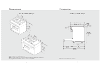
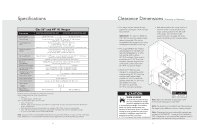
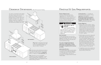
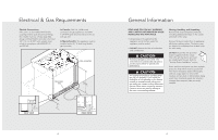
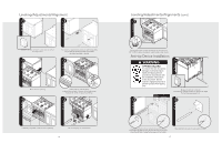
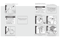
Clearance Dimensions (Wood/Composite Overlay) The bottom of a standard hood should be 30" (76.2 cm) min. to 36" (91.4 cm) max. above the countertop. This would typically result in the bottom of the hood being 66" (167.6 cm) to 72" (182.9 cm) above the floor. Refer to the range hood installation instructions for additional information. These dimensions provide for safe and efficient operation of the hood. WoodO/Cveormlapyosite ((7611268672""t..mmo69 accinmmx..)) WoodO/Cveormlapyosite ((631822..o0647r""ccmm)) (00c"m) 33((796061""..t24mmoccaimmnx.)). ((7611268672""t..mmo69 accinmmx..)) (763.20"cm) (156.2"cm) 33((796061""..t24mmoccaimmnx.)). Wall Installation Note: Minimum clearance for back wall is 3/8" (0.9 cm) with backguard or highshelf. See Standoff Spacer Removal section to allow 0" clearance. Island Installation Note: This range comes standard with an Island Trim. There must be a minimum of 6" (15.2 cm) clearance from rear of range to a combustible wall or 0" clearance to a non-combustible wall. Note: Clearances from non-combustible materials are not part of the ANSI Z21.1 scope and not certified by CSA. Clearances to noncombustible materials must be approved by the authority having jurisdiction. 10 Electrical & Gas Requirements Electrical Requirements Check your national and local codes regarding this unit. This range requires 120VAC/60 Hz; 4 ft. (121.9 cm), 3-wire cord with grounded 3-prong plug attached to unit. See "Electrical Connection" section for grounding instructions. Must be fused seperately from any other circuit. WARNING ELECTRICAL SHOCK HAZARD To avoid the risk of electrical shock, personal injury or death; verify electrical power is turned off at the breaker box and gas supply is turned off until the range is installed and ready to operate, installation by an authorized installer only. Gas Connection The gas supply (service) line must be the same size or greater than the inlet line of the appliance. This range uses a 1/2" (1.3 cm) ID NPT (Sch40) inlet. Sealant on all pipe joints must be resistive to LP gas. The range is designed specifically for natural gas or liquid propane (LP) gas. Before beginning installation verify that the model is compatible with the intended gas supply. Manual shut-off valve: This installer-supplied valve must be installed in the gas service line before the appliance in the gas stream and in a location where it can be reached quickly in the event of an emergency. Any opeing behind the range shall be sealed. In Massachusetts: A "T" handle type manual valve must be installed in the gas supply line to the appliance. IMPORTANT: Any conversion required must be performed by your dealer or a qualified licensed plumber or gas service company. Please provide the service person with this manual before work begins. Pressure Regulator: • All heavy-duty, commercial type cooking equipment must have a pressure regulator on the incoming service line for safe and efficient operation, since service pressure may fluctuate with local demand. External regulators are not required on this range since a regulator is built into each unit at the factory. Under no condition bypass this built-in regulator. • Manifold pressure should be checked with a manometer, natural gas requires 5.0" W.C.P. and LP gas requires 10.0" W.C.P. Incoming line pressure upstream from the regulator must be 1" W.C.P. higher than the manifold pressure in order to check the regulator. The regulator used on this range can withstand a maximum input pressure of 1/2" PSI (14.0" W.C.P.). If the line pressure is in excess of that amount, a step down regulator will be required. • The appliance must be disconnected from the gas supply piping system during any pressure testing of that system. 11
-
 1
1 -
 2
2 -
 3
3 -
 4
4 -
 5
5 -
 6
6 -
 7
7 -
 8
8 -
 9
9 -
 10
10 -
 11
11 -
 12
12
 |
 |
