Viking DGRT3014BBK Installation Instructions - Page 7
Initial Ignition of Burners For Sealed Surface Burners
 |
View all Viking DGRT3014BBK manuals
Add to My Manuals
Save this manual to your list of manuals |
Page 7 highlights
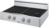
Grill/Griddle Burner Adjustment 12" Grill Assembly 24" Grill Assembly Grill 1. The grill burner orifice and air shutter are located beneath the front 1 end of the grill assembly. To gain access to the adjustment, remove the grill grate, grate support, flame spreaders, and the burner shield. 2. Remove the screw at the front and rear of the burner. 2 3. Lift the burner off the orifice and locate the air shutter adjustment 3 screw at the end of the burner. (See Detail "A") 4. Loosen the screw and adjust the air shutter to the desired setting [for 4 natural gas open shutter approximately 7/16" (1.1 cm); for LP gas open the air shutter approximately 3/8" (.95 cm)]. 5 5. Tighten the screw, then replace the burner on the orifice. 6. Check the flame for desired height before replacement of the above 6 parts. 7. The flame adjustments are the same as the surface burners. Use a 1/2" (1.3 cm) deep socket to adjust the orifice head; turn clockwise to 1. Grill Grates decrease flame and counter clockwise to increase flame. 2. Flavor Generator plates 3. Heat Deflector Grill Burner 4. Grill Frame Screw (Rear of Burner) Screw (Front of Burner) 5. Grill Burner Sheild (Do not remove from burner) 6. Burner (Do not remove) Detail A Air Shutter Adjustment Screw Griddle 1. To gain access to the burner orifice and air shutter, remove grates and grate supports located on either side of the griddle. Lift and remove the griddle. CAUTION: Before fully removing the griddle assembly, lift the griddle assembly approximately 4" above the griddle box. Carefully remove the temperature probe from the probe bracket. (See Detail "B") Make note of the position of the temperature probe so it can be reinstalled properly. Failure to properly reinstall can result in damage to the temperature probe. 2. Carefully remove the ignitor and put to the side. 3. Remove the metal plate located below the burner. 4. Remove the screws at the front and rear of the burner, remove the burner tube and locate the air shutter adjustment screw at the end of the burner tube. 5. Flame adjustments are the same as the grill #4-#7. 6. Replace all griddle parts and griddle. Probe Bracket Griddle Burner Detail B 11 Initial Ignition of Burners (For Open Surface Burners) All rangetops are tested before leaving the factory. Field adjustments may be necessary for proper mixture of gas and air for proper operation. When the rangetop is connected to gas and electric service, it should be adjusted by a qualified technician. When adjustments are required, contact your dealer/installer for corrections. If assistance is not available, contact Viking Range Corporation Preferred Service for the nearest authorized service agent at (662) 451-4133. All corrections to installation are the responsibility of the dealer/installer or end user. Initial Ignition of Burners (For Sealed Surface Burners) All sealed top rangetops are tested before leaving the factory. There are no adjustments for the sealed surface burners if connected according to the information on the rating plate. Check each burner for proper operations. Flames should be blue in all settings. If service is required, contact your dealer for the name of their authorized service agency. If none is available, contact Viking Preferred Service for the nearest authorized service agency in your area. Gas conversions and initial installation are not the responsibility of the manufacturer. Cleaning and Maintenance Surface Burners Wipe up spill-overs as soon as possible after they occur and before they get a chance to burn in and cook solid. In the event of a spill-over, follow these steps: 1. Allow the burner and grate to cool to a safe temperature level. 2. Lift off the burner grate. Wash in warm soapy water. 3. Remove the burner cap and burner head and clean per instructions below. 4. Wipe up any spills which remains on the sealed top surface. 5. Replace burner cap, burner head, and grates, after drying thoroughly. Note: When replacing burner head, arrow must be pointing towards back of range. 12
-
 1
1 -
 2
2 -
 3
3 -
 4
4 -
 5
5 -
 6
6 -
 7
7 -
 8
8
 |
 |
