Viking DMOR200SS Installation Instructions
Viking DMOR200SS Manual
 |
View all Viking DMOR200SS manuals
Add to My Manuals
Save this manual to your list of manuals |
Viking DMOR200SS manual content summary:
- Viking DMOR200SS | Installation Instructions - Page 1
to see that there is a Wall TEMPLATE and Top CABINET Template. Read enclosures and SAVE the Use and Care manual. Check the oven for any damage, or Viking AUTHORIZED SERVICER. 1 Mounting Space This Built-in Microwave Hood requires a mounting space on a wall as shown in Figure 1. It is designed to - Viking DMOR200SS | Installation Instructions - Page 2
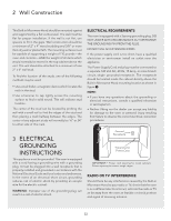
be capable of supporting a weight of 110 pounds-the oven and contents-AND the weight of all items Microwave Hood mounting location as shown in figure 2. NOTE: • If you have any questions about the grounding or electrical instructions, consult a qualified electrician or serviceperson. • Neither Viking - Viking DMOR200SS | Installation Instructions - Page 3
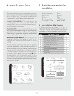
#10 - 24 x 50 mm Top Cabinet Screw 5 x 85 mm Tapping Screw 4 x 12 mm Flat Washer 30 mm diameter Rear Cushion Exhaust Damper Assembly Scale Plate Grease Filter QTY 4 4 2 1 2 1 1 2 2 figure Parts Included Parts shown not to common scale. E3 - Viking DMOR200SS | Installation Instructions - Page 4
This Built-in Microwave Hood is designed for adaptation to three types of hood ventilation systems. Select the type required for your installation. RECIRCULATING - non-vented, ductless. Follow installation procedure (A). Recirculating requires the use of the Charcoal Filter, which has already - Viking DMOR200SS | Installation Instructions - Page 5
the cavity. The Fan Cover Bracket and Exhaust Damper Assembly are mounted to the wall. Follow instructions on WALL TEMPLATE provided. (C) Vertical Exhaust: Outside Ventilation 9 figure 2) VERTICAL EXHAUST: Lift Hood Fan Unit carefully and slip wires out of cavity. • CAUTION: Do not pull or stretch - Viking DMOR200SS | Installation Instructions - Page 6
center of the Fan Cover Bracket, which were removed in Step 1. The Hood Fan Unit is now rotated for vertical exhaust operation. $ 7 Exhaust Damper Assembly INSTRUCTIONS FOUND ON WALL AND TOP CABINET TEMPLATES. The next step is to read and follow mounting information on wall and top cabinet templates - Viking DMOR200SS | Installation Instructions - Page 7
9 Oven Installation ( Space more than wall thickness 10 Mounting Oven to the Wall Utilization of the carton may make installation easier. ~ figure figure figure Wall 2) MOUNTING PLATE: Position the Mounting Plate with the Toggle Bolts attached at the wall location and insert Toggle Nuts and - Viking DMOR200SS | Installation Instructions - Page 8
OVEN TO THE WALL: Attach the two Bottom Plate Screws saved from section PREPARATION OF THE OVEN, Figure 4. Install the two Grease Filters 9. Viking Range Corporation 111 Front Street Greenwood, Mississippi 38930 USA (662) 455-1200 For product information, call 1-888-VIKING1 (845-4641) or visit - Viking DMOR200SS | Installation Instructions - Page 9
quelconque dommage, ne faites pas fonctionner le four et contactez votre revendeur ou UN SERVICE AGRÉÉ DE DÉPANNAGE VIKING. Reportez-vous aux instructions d'installation pour plus de détails. 1 Espace de Support Le Schéma 1 vous montre l'espace de montage nécessaire à ce four à micro-ondes à hotte - Viking DMOR200SS | Installation Instructions - Page 10
po (9,5 mm) d'épaisseur. Les surfaces de montage doivent pouvoir supporter un poids de 110 lb. (50 kg) - le four ou à 61 cm) de chaque côté de cette marque. 3 INSTRUCTIONS DE MISE À LA TERRE Cet appareil doit être mis à ou un réparateur qualifié. • Ni Viking ni le revendeur ne peuvent accepter aucune - Viking DMOR200SS | Installation Instructions - Page 11
4 Conduit d'évacuation à la 5 Outils recommandés pour Hotte l'installation Pour une hotte avec évacuation à l'air libre, il faut installer un conduit d'évacuation à la hotte. Tous les conduits doivent être en métal; n'employez aucun conduit en plastique. Vérifiez que toutes les connexions sont - Viking DMOR200SS | Installation Instructions - Page 12
7 Préparation du four Détachez la plaque de montage du four en retirant deux vis.Voir l'illustration ci-dessous. Conservez ces vis pour les utiliser à la section MONTAGE MURAL DU FOUR, étape /. 4 (B) Échappement Horizontal : Ventilation extérieure 5 schéma Plaque de montage schéma Arrière du - Viking DMOR200SS | Installation Instructions - Page 13
Faites attention de ne pas pincer le fil et l'unité de ventilation de hotte. Voir le (B) du Schéma 7. 8 Conservez le support de fermeture de ventilateur pour des instructions ultérieures. schéma ! schéma schéma 4) ÉCHAPPEMENT HORIZONTAL: Placez le fil de connexion dans le coffret de fils. La - Viking DMOR200SS | Installation Instructions - Page 14
2 vis du bord arrière et les 3 vis du centre supérieur du support de couverture de ventilateur, qui ont été enlevées à l'étape 1 précédente. schéma CE FOUR NE PEUT PAS ÊTRE INSTALLÉ CORRECTEMENT SANS SE REPORTER AUX INSTRUCTIONS DE MONTAGE PORTÉES SUR LES GABARITS DE COFFRET DE MONTAGE MURAL ET AU - Viking DMOR200SS | Installation Instructions - Page 15
10 Montage Mural du Four L'utilisation du carton peut faciliter l'installation. ( Deje espacio ~ superior al espesor de pared schéma schéma schéma Pared 2) PLAQUE DE MONTAGE: Positionnez la plaque de montage avec les boulons à ailettes sur l'emplacement mural et insérez l'extrémité des - Viking DMOR200SS | Installation Instructions - Page 16
conservées lors de l'étape 4. Poser les deux filtres à graisse 9. Viking Range Corporation 111 Front Street Greenwood, Mississippi 38930 USA (662) 455-1200 Pour Assurez-vous que l'appareil a été installé en suivant toutes les instructions et en utilisant le gabarit mural et de plafond. • Branchez le - Viking DMOR200SS | Installation Instructions - Page 17
página 2. Desempaque y Revisión de su horno Abra la parte inferior de la caja de cartón, doble hacia atrás las . Lea los documentos anexos y GUARDE el Manual de Operación. Revise el horno en cuanto distribuidor o PROVEEDOR DE SERVICIO AUTORIZADO DE Viking. Véase las Instrucciones de Instalación para - Viking DMOR200SS | Installation Instructions - Page 18
en la Figura 2. NOTA: • Si tiene preguntas acerca de las instrucciones eléctricas o de conexión a tierra, consulte un electricista calificado. • Ni Viking ni el distribuidor pueden aceptar ninguna responsabilidad por daño al horno o por lesiones personales resultantes de no seguir los procedimientos - Viking DMOR200SS | Installation Instructions - Page 19
las transiciones y adaptadores más la longitud de todas las secciones rectas de ducto. La Figura 3 muestra la longitud equivalente aproximada en pies de algunas partes de ducto típicas. Utilice los valores dentro de paréntesis para calcular la resistencia al flujo de aire equivalente que debe ser un - Viking DMOR200SS | Installation Instructions - Page 20
Posterior del Microondas 1) ESCAPE HORIZONTAL: Remueva los 2 tornillos del borde trasero y los 3 tornillo de la parte central superior de la Cubierta del Ventilador. Guarde 2 tornillos a utilizar posteriormente y deseche el tercer tornillo restante. Remueva la Cubierta del Ventilador deslizándola - Viking DMOR200SS | Installation Instructions - Page 21
de modo que las aberturas de aspas del ventilador queden dirigidas hacia la parte trasera del horno. 7 (A). Coloque nuevamente la Unidad de Ventilador de los 2 tornillos del borde trasero y los 3 tornillo de la parte central superior de la Cubierta del Ventilador. Remueva la Cubierta del Ventilador - Viking DMOR200SS | Installation Instructions - Page 22
figura figura 4) ESCAPE VERTICAL: Sujete la Cubierta del Ventilador a la unidad mediante los 2 tornillos del borde trasero y los 3 tornillos de la parte central superior de la Cubierta del Ventilador, que se removieron en el Paso 1 anterior. La Unidad de Ventilador de la Campana Extractora ahora - Viking DMOR200SS | Installation Instructions - Page 23
9 Instalación del Horno ( Deje espacio superior al espesor de pared 10 Montaje del Horno en la Pared Utilization of the carton may make installation easier. ~ figura figura figura Pared 2) PLACA DE MONTAJE: Coloque la Placa de Montaje con los Pernos de Anclaje sujetados, en el sitio de pared e - Viking DMOR200SS | Installation Instructions - Page 24
con la parte inferior de la Placa de Montaje. 9 Tornillos de la placa inferior 6) MONTAJE DEL HORNO EN LA PARED: Ajuste los tornillos de la placa inferior que guardo previamente de acuerdo a las indicaciones de la sección PREPARACIÓN DEL HORNO. Instale los dos Filtros de Grasa 9. Viking Range
-
 1
1 -
 2
2 -
 3
3 -
 4
4 -
 5
5 -
 6
6 -
 7
7 -
8
-
9
-
10
-
11
-
12
-
13
-
14
-
15
-
16
-
17
-
18
-
19
-
20
-
21
-
22
-
23
-
24
 |
 |
Viking Installation Guide
Designer Built-In Microwave Hood
111 Front Street
Greenwood, Mississippi 38930 USA
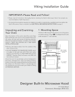
IMPORTANT–Please Read and Follow!
• Please read all instructions thoroughly before installing the Built-In Microwave Hood. Two people are
recommended to install this product.
• If a new electrical outlet is required, its installation should be completed by a qualified electrician before the
Built-In Microwave Hood is installed. See
ELECTRICAL GROUNDING INSTRUCTIONS
on page 2.
Open the bottom of the carton, bend the carton flaps
back and tilt the oven over to rest on plastic foam pad.
Lift carton off oven and remove all packing materials,
Wall and Top Cabinet Template, Turntable, and Turntable
Support. SAVE THE CARTON AS IT MAY MAKE
INSTALLATION EASIER.
• Remove the feature sticker from the outside of the
door, if there is one.
• DO NOT REMOVE THE WAVEGUIDE COVER, which
is located on the right side wall of the oven cavity.
Check to see that there is a Wall TEMPLATE and Top
CABINET Template. Read enclosures and SAVE the
Use and Care manual.
Check the oven for any damage, such as misaligned or
bent door, damaged door seals and sealing surfaces,
broken or loose door hinges and latches and dents inside
the cavity or on the door. If there is any damage, do
not operate the oven and contact your dealer or Viking
AUTHORIZED SERVICER.
Unpacking and Examining
Your Oven
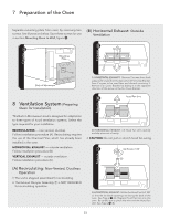
1 Mounting Space
This Built-in Microwave Hood requires a mounting space
on a wall as shown in Figure
1
. It is designed to be used
under standard 12" wall cabinets.
Backguard
At least 2"
15.5"
30"
12"
36" or more
from cooking
surface
72" or more
from floor
1