Viking FPIM515 Installation Instructions - Page 9
Caution - ice maker
 |
View all Viking FPIM515 manuals
Add to My Manuals
Save this manual to your list of manuals |
Page 9 highlights
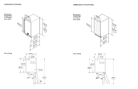
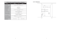
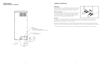
WATER & DRAIN INSTALLATION The recommended water supply tubing is 1/4" OD copper. Stainless steel flex or reinforced PVC tube may also be used. Install an easily accessible shut-off valve between the supply and the unit. This shut-off valve should not be installed behind the unit. Note: DO NOT use self-piercing type valves. 1. Remove the front service access panel by removing the screw. 2. Route the tubing through the right hole in the back to the inlet water solenoid valve inlet. 3. Install a compression fitting on the tubing and connect to the inlet of the solenoid (fitting is located in cloth bag behind access panel). Service Access Panel Screw DRAINS There are two types of ice machine models, one that drains by gravity and one that has an internal drain pump. Drain Pump Model drain installation 1. Locate the coil of 3/8" ID plastic drain tubing secured to the back of the unit. 2. Route the plastic drain tube from the back of the unit to the drain connection point. IMPORTANT NOTE: Often an air gap is required by local codes between the ice maker drain tube and the drain receptacle. Water Inlet Tube (field supplied) Drain Tube, Route to building drain Back View, Drain Pump Model Gravity Drain Pump Model drain installation CAUTION Restrictions in the drain system to the machine will cause water to back up into the ice storage bin and melt the ice. Gravity drain tubing must be vented, have no kinks and slope to the building drain. Air gaps are typically required by local code. 1. Place the ice machine in front of the installation opening. Adjust leveling legs to the approximate height. 2. Remove the front service access panel and the upper back panel (if necessary). Note: If you are connecting a gravity drain model and the drain opening has been located in the floor under the base pan according to the pre install specifications, follow steps 3 through 5 to drain the unit through the base. If not, proceed to step 6b. 3. Remove the clamp and barbed elbow and take off the plastic cover in the base pan below the drain hose. 4. Connect a straight 5/8" barbed connector to the drain hose, securing with the clamp removed in step 4. 5. Cut an 8" piece of 5/8" ID X 7/8" OD tygon (clear plastic) tubing. Slide one end of the tube onto the outlet of the barbed connector and secure with a clamp. Leave the other end of the tube lying on the floor of the base pan until the unit is positioned over the floor drain. 6. Route the drain tube. Either a) Insert the drain tube through the base pan into the floor drain or b) Route the drain tube through the left hole in the lower back panel and connect to barbed elbow and secure with a clamp. 7. Reinstall the upper back panel (if removed in step 2). 8. Reinstall the service access panel. Level the unit. Drain Hose Barbed Elbow Water Inlet Tube (field supplied) Drain Hose, Route to building drain Back View, Gravity Drain Model 16 17
-
 1
1 -
2
-
3
-
 4
4 -
 5
5 -
 6
6 -
 7
7 -
 8
8 -
 9
9 -
 10
10
 |
 |
