Viking FWCI1240GR Installation Instructions - Page 9
Installation, Anti-Tip Brackets
 |
View all Viking FWCI1240GR manuals
Add to My Manuals
Save this manual to your list of manuals |
Page 9 highlights
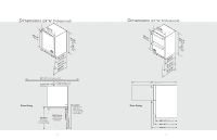
Anti-Tip Brackets WARNING Unit may tip forward if loaded racks/shelves are all pulled out at the same time. To prevent tipping and provide a stable installation, the unit must be secured in place with the anti-tip brackets provided with the unit. A set of metal anti-tip brackets are supplied with the unit. The anti-tip brackets, when properly installed should secure the rear legs and prevent the unit from tipping forward. Some installation sites may require modification to provide a secure surface for attaching the brackets. Refer to the illustrations below for mounting bracket locations. IMPORTANT: If installing on a concrete floor, concrete fasteners are required and not included with the anti-tip kit. Anti-tip Bracket ø 3/8" (1.0 cm) 15/16" (2.4 cm) 3/16" (0.5 cm) 13-1/2" (34.3 cm) 15/16" (2.4 cm) 3/16" (0.5 cm) 22-1/32" (56.0 cm) FRONT OF UNIT FRONT OF UNIT 16 Installation CAUTION Any finished flooring should be protected with appropriate material to avoid damage from moving the unit. If unit has been laid on its back or sides, place unit upright and allow minimum of 24 hours before connecting power.Re-installl the doors by removing the upper pivot pin completely, sliding the door onto the lower pivot pin and re-installing the upper pivot pin and fastening tightly. Before moving the unit, make sure the door is secured to the cabinet (tape may be required to hold the doors closed). 1. Plug the unit into the 15 amp grounded outlet located in the installation opening. With power applied to the unit, check that the lighting and cooling function operate properly, then turn off power to the wall outlet at the circuit breaker. WARNING Shut off power to the wall outlet before installing into the opening. 2. Check that the following are level and square: • Front face and interior opening • Installation opening and floor surface • Countertop bottom front edge IMPORTANT: Leveling legs should not be extended more than 3/4" from bottom of the cabinet. IMPORTANT: The floor under the unit must be at the same level as the surrounding finished floor. 3. If all surfaces are level: a. Measure from the floor to the bottom of the front edge of the countertop b. Measure the rear of the unit cabinet from the floor to top of cabinet, at back corners c. Adjust rear legs so B measurement equals A measurement. Using an adjustable wrench or pliers, turn legs counterclockwise to raise the unit or clockwise to lower the unit 4. Slide the cabinet into position, making sure the rear cabinet leveling legs slide under the anti-tip devices. Push the cabinet into the opening until the bottom front edge of the cabinet is flush with the surrounding cabinetry or the leveling legs are tight with the anti-tip devices. IMPORTANT: The rear cabinet leveling legs must be engaged under the anti-tip brackets. 5. Shim the front of the unit so the front face is flush with surrounding cabinetry. Adjust the front legs to support the countertop at the shimmed height. Using an adjustable wrench or pliers, turn legs counterclockwise to raise the unit or clockwise to lower the unit. Countertop should be resting on top of the unit. IMPORTANT: If countertop is not resting entirely on unit top, shim the countertop to prevent damage to the countertop. CAUTION To prevent damage to the countertop and unit underneath, do not place heavy objects on countertop directly above the unit. 17
-
 1
1 -
2
-
3
-
 4
4 -
 5
5 -
 6
6 -
 7
7 -
 8
8 -
 9
9 -
 10
10 -
 11
11 -
 12
12
 |
 |
