Viking VBI7360W Installation Instructions
Viking VBI7360W Manual
 |
View all Viking VBI7360W manuals
Add to My Manuals
Save this manual to your list of manuals |
Viking VBI7360W manual content summary:
- Viking VBI7360W | Installation Instructions - Page 1
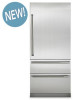
Installation Guide Integrated Refrigerator / Freezer 7 SERIES VBI7360 / CVBI7360 FBI7360 / CFBI7360 MVBI7360 / CMVBI7360 MFBI7360 / CMFBI7360 - Viking VBI7360W | Installation Instructions - Page 2
Unit 17 Kickplate Installation 17 Flush Mount Side Trim 18 Door Stop Adjustment 19 System Specifications and Data 21 Performance Checklist 21 Control Panels 21 Service & Registration 22 2 - Viking VBI7360W | Installation Instructions - Page 3
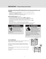
provided many important safety messages in this manual and on your appliance. ALWAYS read you what can happen if the instructions are not followed. It is prevent the unit from being serviced. • make sure that you valve) • assure that floor will support unit, door panels and contents (approximately - Viking VBI7360W | Installation Instructions - Page 4
• Viking Range, LLC will NOT warranty any problems resulting from GFI outlets which are not installed properly is completely installed and secured per installation instructions. Use two or more people to used to turn the power off when cleaning or servicing the refrigerator. To turn power off, remove - Viking VBI7360W | Installation Instructions - Page 5
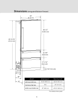
Dimensions (Integrated Bottom-Freezer) 36" (91.4 cm) 83-15/16" (213.2 cm) 50-1/2" (128.3 cm) 12-1/8" (30.8 cm) (5272.2-1c/m2") B* A 17-1/16" (43.3 cm) 4-1/16" (10.3 cm) Model VBI7360/CVBI7360 FBI7360/CFBI7360 MVBI7360/CMVBI7360 Dimension A 27-3/8" (69.5 cm) N/A Dimension B* 24-3/4" (62.9 cm) - Viking VBI7360W | Installation Instructions - Page 6
Specifications (Integrated Bottom-Freezer) 36" Integrated Refrigerator/Freezer Description VBI7360 / CVBI7360 MVBI7360 / CMVBI7360 Overall width Overall height (from bottom) Overall depth from rear Cutout width Cutout height Cutout depth Electrical requirements Maximum amp usage Inlet water - Viking VBI7360W | Installation Instructions - Page 7
Cutout Dimensions (Bottom-Freezer) (632.55c"m) Can be located on either side * (o2p1e3n.4in8cg4m"h)emigihnt. (o2p1e86n5.3i-nc3gm/h1)e6mi"gahxt. Electric Outlet Location (1395.-41c/m2") (140-.1+8/c4m" ) dliemveenlinsigon Water Line Entry Area (913.56c"m) (91.5 c3m6") *Note: For all models, 3" - Viking VBI7360W | Installation Instructions - Page 8
Tipping Radius 1050 900 9-1/2" (24.1 cm) 37-1/4" (94.6 cm) 39-5/16" (99.8 cm) 36" (94.4 cm) 127-3/16" (323.1 cm) 83-15/16" (213.2 cm) 91-7/16" (232.3 cm) 111-3/16" (323.1 cm) 24-5/8" (62.5 cm) 87-3/4" (222.9 cm) 83-15/16" (213.2 cm) 17-1/4" (43.8 cm) 8 - Viking VBI7360W | Installation Instructions - Page 9
top heavy and tips easily when not completely installed. To avoid a hazard due to instability of the appliance, it must be installed according to the instructions including the anti-tip bracket C Cabinet Opening Anti-tip Bracket There are 12 hole locations on the anti-tip bracket. Of those 12, at - Viking VBI7360W | Installation Instructions - Page 10
can be moved around corners and through doorways. • Floors can support unit's weight plus food weight (approximately 1200 pounds [540 kg] cord is damaged, it must be replaced by the manufacturer or it service agent or a qualified service technician in order to avoid a hazard. DO NOT use an extension - Viking VBI7360W | Installation Instructions - Page 11
moving the unit out of enclosure for cleaning or service. Tubing should be soft instead of rigid and ends All four leveling legs must contact the floor to support and stabilize the full weight. • DO NOT move and install unit. Failure to follow this instruction can result in back or other injury. • - Viking VBI7360W | Installation Instructions - Page 12
Moving Unit 1 A Remove shipping brackets from skid by removing four bolts (two on each side) with a 1/2" (1.3 cm) deep-well socket wench and a pair of pliers. Note: Tilting unit is not required to remove shipping brackets. Slip appliance dolly between unit and skid. Remove unit from skid. Note: - Viking VBI7360W | Installation Instructions - Page 13
Optional Custom Front Panels - Dimensions Note: Each panel overlay must be dry, solid, straight one-piece panels. The use of multiple panel pieces to achieve the dimensions is not recommended. Maximum panel weight: Refrigerator door panel - 39 lbs (17.6 kg) Top Freezer drawer panel - 10 lbs (4.5 - Viking VBI7360W | Installation Instructions - Page 14
Optional Custom Front Panels - Install In order to access the mounting holes, unsnap panel trim on both sides of all three doors. Panel trim Mounting screws go thru "C" channel bracket on the side of the door and then thru the back of custom F panel (2 per panel) 14 - Viking VBI7360W | Installation Instructions - Page 15
and tips easily when not completely installed. To avoid a hazard due to instability of the appliance, it must be installed according to the instructions including the anti-tip bracket Ensure you have approximately 6 ft. (1.8 m) of 1/4" (6 mm) copper tubing available at the right rear side of the - Viking VBI7360W | Installation Instructions - Page 16
Water Line Installation With the refrigerator in line with the cutout, but outside of the cabinetry, insert the copper tubing through the indicated hole. Push the copper tubing through the machine compartment until it comes out the front side of the refrigerator. Roll the refrigerator into place in - Viking VBI7360W | Installation Instructions - Page 17
Leveling Unit Once the unit is in position, height adjustment can be made from the front. Remove panel just below the water filter. Using a 5/16" hex drive, turn clockwise to raise the unit or counterclockwise to lower. Use the lowest torque setting when using a power drill. Do not turn the - Viking VBI7360W | Installation Instructions - Page 18
Flush Mount Side Trim After the unit has been placed in the cutout, leveled and all connections completed, the unit will need to be fastened to the cabinetry. Open the door and remove the drawers. Using the flat wood screws, fasten the unit to the cabinetry on both sides. NOTE: Only use the screws - Viking VBI7360W | Installation Instructions - Page 19
Door Stop Adjustment Your refrigerator is factory set at a 90o degree opening. The 90 degree door stop opening is shown in the illustration below with the long end of the door stop facing away from the door. To change to 105o door stop, locate the door stop on top of the door hinge. Remove the two - Viking VBI7360W | Installation Instructions - Page 20
performance may vary. Must be installed and operated in accordance with manufacturer's recommended procedures and guidelines. Installation instructions, parts and service availability, and standard warranty are included with the product when shipped. This drinking water system must be maintained - Viking VBI7360W | Installation Instructions - Page 21
Performance Checklist -Verify cabinet size. -Verify electrical supply and water supply (if applicable). -Install anti-tip device(s) and verify unit is secure. -Position unit in cutout, level at desired height and secure unit. -Plug-in unit and verify operation. -Connect water supply (if applicable). - Viking VBI7360W | Installation Instructions - Page 22
problem that you are having. If you are unable to obtain the name of an authorized service agency, or if you continue to have service problems, contact Viking Range, LLC at 1-888-(845-4641), or write to: VIKING RANGE, LLC PREFERRED SERVICE - Viking VBI7360W | Installation Instructions - Page 23
23 - Viking VBI7360W | Installation Instructions - Page 24
Viking Range, LLC 111 Front Street Greenwood, Mississippi 38930 USA (662) 455-1200 For product information, call 1-888-(845-4641) or visit our web site at vikingrange.com UL C UL 055156-000F EN (033120)
-
 1
1 -
 2
2 -
 3
3 -
 4
4 -
 5
5 -
 6
6 -
 7
7 -
8
-
9
-
10
-
11
-
12
-
13
-
14
-
15
-
16
-
17
-
18
-
19
-
20
-
21
-
22
-
23
-
24
 |
 |
Installation
Guide
Integrated Refrigerator / Freezer
7 SERIES
VBI7360 / CVBI7360
FBI7360 / CFBI7360
MVBI7360 / CMVBI7360
MFBI7360 / CMFBI7360