Viking VBI7360W Installation Instructions - Page 11
Area Requirements, Tip Over Hazard, Unpacking Unit
 |
View all Viking VBI7360W manuals
Add to My Manuals
Save this manual to your list of manuals |
Page 11 highlights
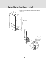
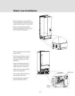
General Information • Viking Range, LLC is not responsible for property damage due to improper installation or water connection. • Connect 1/4" (6 mm) flexible copper tubing to household plumbing in compliance with local codes and ordinances. • Length of copper tubing must reach from water supply connection to the unit connection with an additional length to facilitate moving the unit out of enclosure for cleaning or service. Tubing should be soft instead of rigid and ends should be free of burrs. • Copper tubing route must be above 35º F (1.7º C) to prevent water line from freezing. • DO NOT use plastic water lines from the household plumbing to the water inlet valve connection on the refrigeration unit. • DO NOT use the self-piercing feature of a saddle valve. The hole made by the piercing lance is too small for the water flow rate required by the ice maker. • If saddle valve is not used, place a separate shutoff valve in an easily accessible location between water supply and the unit. DO NOT install shut-off valve behind the unit. • The installation of Viking Range, LLC units with a reverse osmosis system is acceptable as long as the water pressure remains within the allowable PSI as stated below. It is important to note that with many reverse osmosis systems, the pressure starts off high, but then it decreases as the water level of the reverse osmosis storage area drops. This must be considered when checking the water pressure coming into the unit. • Connect to a vertical or horizontal 1/2" (1.3 cm) to 1-1/4" (3.2 cm) COLD water line near water area. • Run water line through the floor, back, or side wall in area shown on page 7. Connect to water supply coming from back of unit on the left side. • Water pressure must be greater than 20 psi and less than 120 psi on non-dispenser units and greater than 35 psi and less than 120 psi on dispenser units. Area Requirements • Most of the unit's weight is at the top. Extra care is needed when moving the unit to prevent tipping. • DO NOT remove protective film until unit is in operating position. • All four leveling legs must contact the floor to support and stabilize the full weight. • DO NOT drop unit. • Remove exterior shipping materials prior to moving unit into home, except door latching device. • Use two or more people to move and install unit. Failure to follow this instruction can result in back or other injury. • To avoid personal injury, wear gloves when performing any installation procedure and wear eye protection when cutting metal straps. Tip Over Hazard Appliance is top heavy and tips easily when not completely installed. Keep doors closed until appliance is completely installed and secured per installation instructions. Use two or more people to move and install appliance. Failure to do so can result in death or serious injury. Unpacking Unit 1. Remove top and bottom strap. 2. Remove top cap. 3. Cut carton rear approximately 1/4" (0.6 cm) to 1" (2.5 cm) from right corner with a utility knife extended 1/4" (0.6 cm). 4. Remove carton and exterior packaging. Save cardboard shipping material to protect floor surface when installing unit. Remove anti-tip bracket from front of shipping pallet. Flush mount side trim is taped to the handle side of the unit. 11
-
 1
1 -
2
-
3
-
4
-
5
-
 6
6 -
 7
7 -
 8
8 -
 9
9 -
 10
10 -
 11
11 -
 12
12 -
 13
13 -
 14
14 -
 15
15 -
 16
16 -
17
-
18
-
19
-
20
-
21
-
22
-
23
-
24
 |
 |