Viking VCFW1000 Installation Instructions - Page 2
Tools And Materials You Will Need, Tools And Materials You May Need, Safety Symbols - installation
 |
View all Viking VCFW1000 manuals
Add to My Manuals
Save this manual to your list of manuals |
Page 2 highlights
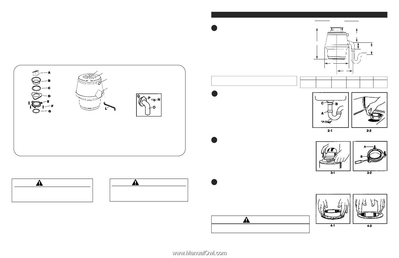
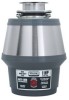
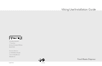
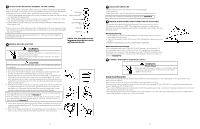
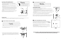
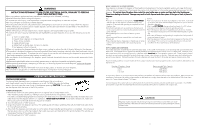
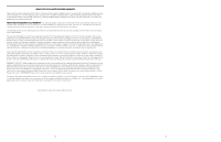
TOOLS AND MATERIALS YOU WILL NEED: Slotted Screwdriver, Adjustable Pliers, Plumber's compound, Electrical Tape TOOLS AND MATERIALS YOU MAY NEED: Phillips Screwdriver, Drain Auger, Hammer, Hacksaw, Pipe Wrench, 3/8 inch Electrical Clamp Connector, Wire Nuts (2), Second 1 1/2 inch Drain Trap, , Water Hose Clamp, Copper Ground Wire, Dishwasher Drain Connection Kit, Air Gap, Electrical On/Off Switch, Drain Tube Extension Read through the complete instructions before installing the disposer. Determine which of the tools and materials you will need before you begin. Make sure you have all necessary disposer parts before installing the disposer (see part identification diagram below). H I J K Mounting Assembly A. Cover/Stopper B. Sink Flange C. Rubber Gaskets (2) D. Pressure Plate E. Upper Mounting Ring F. Screws (3) G. Snap Ring Disposer H. Mounting Gasket/ Splash Baffle I. Lower Mounting Ring J. Dishwasher Inlet K. Discharge Outlet L. Wrenchette Discharge N. Bolt O. Discharge Tube (1 1/2" [3.8 cm] Diameter) P. Flange Q. Gasket SAFETY SYMBOLS CAUTION Caution indicates a potentially hazardous situation which, if not avoided, may result in minor or moderate injury. WARNING Warning indicates a potentially hazardous situation which, if not avoided, could result in death or serious injury. 2 INSTALLATION INSTRUCTIONS 1 CHECK INSTALLATION DIMENSIONS A: Disposer height B: Distance from bottom of sink bowl to centerline of discharge out- let. (Add 1/2 inch[1.3cm] when stainless steel sink is used.) C: Distance from centerline of the discharge outlet to end of dis- charge tube. D: Disposer width E: Distance from disposer vertical centerline to centerline of P-trap connection. F: Centerline of disposer discharge to centerline at waste pipe enter- ing wall. (Dimension "F" must be greater than 1/4 inch [0.6 cm] to prevent standing water in disposer.) B A C F D E If replacing an existing disposer, skip ahead to Instruction 6. If this is a first time installation, continue with Instruction 2. Dimension A B 13 11/16" 6 13/16" (34.8 cm) (17.3 cm) C D 4" 10 1/16" (10.2 cm) (25.6 cm) E 5 3/4" (14.6 cm) 2 DISCONNECT SINK DRAIN 1. Loosen nut (A) at top of "P-trap" with pipe wrench (see Figure 2-1). 2. Loosen nut (B) at top of extension pipe. Remove extension pipe. 3. Loosen nut (C) at base of sink flange. (If nut is corroded or too tight, apply penetrating lubricant.) 4. Push sink flange up through sink hole and remove it (see Figure 2-2). 5. Clean sink flange area of any putty or other material. 3 DISASSEMBLE NEW DISPOSER - MOUNTING ASSEMBLY 1. Insert wrenchette (or screwdriver) into one mounting lug and hold lower mounting ring securely with one hand (see Figure 3-1). With your other hand, turn mounting assembly counterclockwise to remove mounting assembly from lower mounting ring. 2. Turn mounting assembly over (see Figure 3-2) and loosen three mounting screws (A) until you can access snap ring (B). 3. Use screwdriver to pry snap ring off of sink flange. Mounting assembly will now come apart. 4 INSTALL FLANGE IN SINK HOLE Slip one rubber gasket onto sink flange and insert sink flange through sink hole. NOTE: Rubber gasket is preferred sink seal. If sink opening does not permit use of rubber seal, follow steps below to install flange with plumber's compound. 1. Roll 1/4 pound (4 oz. [113g]) of non-hardening plumber's compound to make 3/4 inch (1.9 cm) thick rope to seal around sink flange. 2. Apply putty evenly around sink hole (see Figure 4-1). 3. Press sink flange slowly but firmly into sink drain hole to seat evenly on putty (see Figure 4-2). Use screwdriver or putty knife to scrape all putty from edge of sink hole. CAUTION Do not use plumber's compound on any other disposer connection; it may harm disposer and cause property damage. 3
-
 1
1 -
 2
2 -
 3
3 -
 4
4 -
 5
5 -
 6
6 -
 7
7 -
 8
8
 |
 |