Viking VDSC5606GQSS Installation Instructions - Page 7
Electrical & Gas Requirements
 |
View all Viking VDSC5606GQSS manuals
Add to My Manuals
Save this manual to your list of manuals |
Page 7 highlights
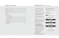
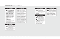
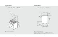
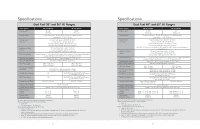
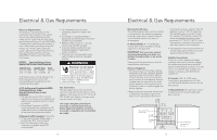
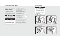
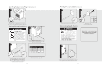
Electrical & Gas Requirements Electrical Requirements This product is manufactured with the neutral terminal connected to the cabinet. Use a 3-wire, agency approved, power supply kit with closed loop terminals rated per the National Electrical Code, ANSI/NFPA 70-latest edition (See Rating chart below). If local codes prohibit grounding through the neutral, use a 4-wire, agency approved, power supply kit with closed loop terminals rated per the National Electrical Code, ANSI/NFPA 70-latest edition (See Rating chart below). RATING* Specified Rating of Power Supply Cord Kit and Circuit Protection 120/240 Volts 120/208 Volts Amps 12.5 - 16.5 KW 9.2 - 12.5 KW 40 or 50 16.5 - 17.5 KW 12.5 - 13.5 KW 50 *The National Electric Code calculation for Electrical Load is less than the Total Connected Electrical Load listed on the model/serial rating plate. A GFI shall be used if required by NFPA70 (National Electric Code), federal/state/local laws, or local ordinances. • The required use of a GFI is normally related to the location of a receptacle with respect to any significant sources of water or moisture. • Viking Range Corporation will NOT warranty any problems resulting from GFI outlets which are not installed properly or do not meet the requirements below. If the use of a GFI is required, it should be: • Of the receptacle type (breaker type or portable type NOT recommended) • Used with permanent wiring only (temporary or portable wiring NOT recommended) • On a dedicated circuit (no other receptacles, switches or loads in the circuit) • Connected to a standard breaker of appropriate size (GFI breaker of the same size NOT recommended) • Rated for Class A (5 mA +/- 1 mA trip current) as per UL 943 standard • In good condition and free from any loose-fitting gaskets (if applicable in outdoor situations) • Protected from moisture (water, steam, high humidity) as much as reasonably possible WARNING Electrical shock hazard. To avoid the risk of electrical shock, personal injury or death; verify electrical power is turned off at the breaker box and gas supply is turned off until the range is installed and ready to operate, installation by an authorized installer only. Gas Connection The gas supply (service) line must be the same size or greater than the inlet line of the appliance. This range uses a 1/2" (1.3 cm) ID NPT (Sch40) inlet. Sealant on all pipe joints must be resistive to LP gas. The range is designed specifically for natural gas or liquid propane (LP) gas. Before beginning installation verify that the model is compatible with the intended gas supply. 12 Electrical & Gas Requirements Manual shut-off valve: The installer-supplied valve must be installed in the gas service line before the appliance in the gas stream and in a location where it can be reached quickly in the event of an emergency. In Massachusetts: A "T" handle type manual valve must be installed in the gas supply line to the appliance. IMPORTANT: Any conversion required must be performed by your dealer or a qualified licensed plumber or gas service company. Please provide the service person with this manual before work begins. Pressure Regulator: • All heavy-duty, commercial type cooking equipment must have a pressure regulator on the incoming service line for safe and efficient operation, since service pressure may fluctuate with local demand. External regulators are not required on this range since a regulator is built into each unit at the factory. Under no condition bypass this built-in regulator. • Manifold pressure should be checked with a manometer, natural gas requires 5.0" W.C.P. and LP gas requires 10.0" W.C.P. Incoming line pressure upstream from the regulator must be 1" W.C.P. higher than the manifold pressure in order to check the regulator. The regulator used on this range can withstand a maximum input pressure of 1/2" PSI (14.0" W.C.P.). If the line pressure is in excess of that amount, a step down regulator will be required. • The appliance must be disconnected from the gas supply piping system during any pressure testing of that system. Flexible Connections: If the unit is to be installed with flexible couplings and/or quick-disconnect fittings, the installer must use a heavy-duty AGA design-certified flexible connector of at least 1/2" (1.3 cm) ID NPT (with suitable strain reliefs) in compliance with ANSI Z21.41 and Z21.69. In Canada: CAN 1-6, 10-88 metal connectors for gas appliances and CAN 1-6.9 M79 quick disconnect devices for use with gas fuel. In Massachusetts: This appliance must be installed with a 36" (3-foot) long flexible gas connector. 2-3/4" (7.0 cm) 2" dia. (5.1 cm) Gas connection in this area 2-1/2" (6.4 cm) 1-3/4" (4.4 cm) 23-7/16" 31-1/16" (59.5 cm) (78.9 cm) 28-5/16" (71.9 cm) 4-3/8" (11.1 cm) Gas or electrical connection in this area 13
-
 1
1 -
 2
2 -
 3
3 -
 4
4 -
 5
5 -
 6
6 -
 7
7 -
 8
8 -
 9
9 -
 10
10 -
 11
11 -
 12
12 -
13
-
14
 |
 |