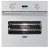
Viking VESO1272SS Installation Instructions - Page 13
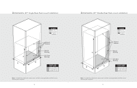
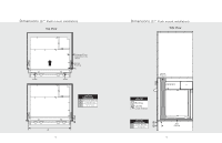
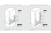
Installation Procedure
 |
View all Viking VESO1272SS manuals
Add to My Manuals
Save this manual to your list of manuals |
Page 13 highlights
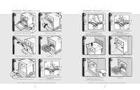
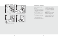
Installation Procedure (continued) 3 4 Remove hinge trim screws. Take off hinge trim. 5 Close until pins stop door. 6 Lift door up and out. Repeat for all doors. 7 Remove racks. 8a Neutral White Green Red Black Unscrew pallet screws from side of oven. Wiring option 1* (connect the white and green to the incoming neutral) *Note: Check local code to see which wiring option should be used when grounding the unit. 24 Installation Procedure (continued) 8b 8c Neutral White Green Red Black Neutral White Green Red Black Wiring option 2* (connect the white to the incoming neutral, attach green to grounded junction box) 9 Wiring option 3* (connect the white to the incoming neutral, attach green to suitable ground) 10 Lift oven into position. 11 Push oven straight in. 12 Attach screws to the side of the framing. Note: 2 screws for single ovens, 4 screws for double ovens (screws not included) Replace racks. *Note: Check local code to see which wiring option should be used when grounding the unit. 25
-
 1
1 -
2
-
3
-
4
-
5
-
6
-
7
-
 8
8 -
 9
9 -
 10
10 -
 11
11 -
 12
12 -
 13
13 -
 14
14 -
 15
15 -
 16
16
 |
 |
