Viking VMOD Flush-mount kit for 24" VMOD MicroDrawer - PMD240FTKSS - Inst - Page 2
Parts Included
 |
View all Viking VMOD manuals
Add to My Manuals
Save this manual to your list of manuals |
Page 2 highlights
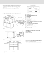
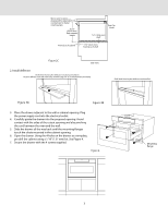
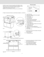
• Read all of the Installation Manual that is included with the DrawerMicro™ Oven before installing in the flush mount configuration. • Observe all governing codes, ordinances, and safety instructions. • Be sure to leave these instructions with the consumer. 1. Prepare cabinet opening as shown in Figures 1, 2A, 2B, 2C. B D F G I K L J A C E H Note: the face of the shelf must sit 1 3/4" (44.45 mm) back from M the face of the cabinet. N shelf face O cabinet face Figure 1 Anti-Tip block Mounting cleat Parts Included Qty. PREF-B019MRP0 Flush Mount 1 2 LX-CZB055MRE0 Mounting screws A. 6" (152.40 mm) B. Suggested electrical outlet location C. Anti-Tip block D. 5" (127 mm) E. 3-1/2" (88.90 mm) F. 4" (101.60 mm) G. 24-3/16" (614.35 mm) minimum 24-1/2" (622.3 mm) maximum H. 14-13/16" (376.24 mm) to bottom of Anti-Tip block I. 1-1/16" (26.97 mm) J. 23-1/2" (596.90 mm) minimum depth K. 22-1/8" (561.97 mm) L. 1-3/4" (44.45 mm) M. 16-7/8" (428.62 mm) opening N. Floor must support 100 lb (45.4 kg) O. 1-3/4" (44.45 mm) A. 22" (558.8 mm) mounting cleat opening width B. 1/4" (6.35 mm) C. 1-1/16" (26.97 mm) Figure 2A A CL Top view Suggested electrical outlet location No oven A B Drawer face B Cabinet C face Anti-Tip block A. 22-1/8" (561.97 mm) mounting cleat opening width B. 24-3/16" (614.35 mm) minimum 24-1/2" (622.3 mm) maximum flush opening width C. 3/4" (19.05 mm) shelf C Figure 2B Front view 2
-
 1
1 -
 2
2 -
 3
3 -
 4
4 -
 5
5 -
 6
6 -
 7
7 -
 8
8
 |
 |
