Viking VMOS201SS Installation Instructions - Page 3
Cabinet or Wall Cutout, Exhaust Duct Assembly - dimensions
 |
View all Viking VMOS201SS manuals
Add to My Manuals
Save this manual to your list of manuals |
Page 3 highlights
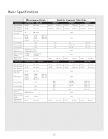
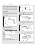
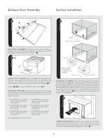
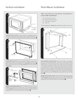
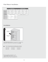
Cabinet or Wall Cutout Exhaust Duct Assembly Provide an opening in the wall or cabinet as indicated in figure 1. The depth should be a minimum of 20-1/8" (51.1 cm). If the Depth (C) dimension is greater than 21" (53.3 cm), the outlet location may be in any area on the rear wall. The floor of the opening should be constructed of plywood strong enough to support the weight of the oven (about 100 lbs.) and should be level for proper operation of the oven. Note: While the proper functioning of the oven does not require that the opening be enclosed (with sides, ceiling and rear partition), this may be required by local code, and it is suggested that the local code be checked for any such requirement. 1 E 2 DUCT (B) DUCT (C) SCREW (A) EXHAUST DUCT ASSEMBLY: Insert the edge of DUCT (B) into the hold lip of DUCT (C). Secure together by using a SCREW (A) provided in the kit. See figure 2. 3 SCREW (A) DUCT (A)-1 DUCT (BC) SCREW (A) A C B EXHAUST DUCT ASSEMBLY: Position DUCT (A)-1 on the top of the D oven inserting edge of DUCT (BC) assembly into hole lip of DUCT (A)-1. Tighten two SCREWS (A), securing DUCT (A)-1 to DUCT (BC) assembly. See figure 3. 4 SCREW (A) DUCT (A)-2 Surface Mount Cutout Dimensions * For flush mount dimensions please see installation template and flush mount installation on page 5-6. CONVECTION CONVENTIONAL (A) Height 18-1/2" (46.9 cm) Min. 16-3/4" Max. 17" (42.5 cm) (43.2 cm) (B) Width 25" (63.5 cm) Min. 24-3/8" (61.9 cm) Max. 24-11/16" (62.7 cm) (C) Depth Min. 20-1/8" (51.1 cm) Min. 20-1/8" (51.1 cm) Min. 6" (15.2 cm) (D) Max. 11-1/2" (29.2 cm) Min. 4" (10.2 cm) (E) Max. 5" (12.7 cm) ELECTRICAL OUTLET LOCATION: Outlet should NOT be in the shaded area as indicated on figure 1. At the rear of the opening, provide a 3-pronged, polarized, electrical outlet, 115-120 volt AC, 15 amp or larger. SCREW (A) DUCT (A)-1 EXHAUST DUCT ASSEMBLY: Position DUCT (A)-2 on the top of the oven and insert it into the hold lip of DUCT (A)-1. Secure DUCT (A)-2 to DUCT (A)-1 using two SCREWS (A) provided. See figure 4. 5 SCREW (A) SCREW (A) DUCT (A)-3 SCREW (A) DUCT (A)-2 EXHAUST DUCT ASSEMBLY: Position DUCT (A)-3 on top of the oven and insert it into DUCT (A)-2. Secure DUCT (A)-3 using three screws (A) provided. See figure 5. E3
-
 1
1 -
 2
2 -
 3
3 -
 4
4 -
 5
5 -
 6
6 -
 7
7 -
 8
8 -
 9
9 -
10
-
11
-
12
-
13
-
14
-
15
-
16
-
17
-
18
-
19
-
20
 |
 |
