Viking VSOC530 Installation Instructions
Viking VSOC530 Manual
 |
View all Viking VSOC530 manuals
Add to My Manuals
Save this manual to your list of manuals |
Viking VSOC530 manual content summary:
- Viking VSOC530 | Installation Instructions - Page 1
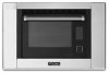
Installation Guide Built-in Combi Steam/Convect™ Oven MVSOC530SS - Viking VSOC530 | Installation Instructions - Page 2
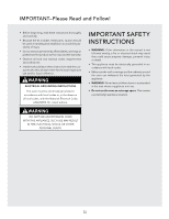
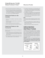
or, in the absence of local codes, with the National Electrical Code, ANSI/NFPA 70 - latest edition. IMPORTANT SAFETY INSTRUCTIONS • WARNING: If the information in this manual is not followed exactly, a fire or electrical shock may result that could cause property damage, personal injury or death - Viking VSOC530 | Installation Instructions - Page 3
all of the Installation Guide before installing the oven. • Remove all packing material before connecting the electrical supply. • Observe all governing codes and ordinances. • Be sure to leave these instructions with the consumer. Important Notes to the Consumer Keep this manual with your Use and - Viking VSOC530 | Installation Instructions - Page 4
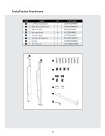
Installation Hardware ITEM 1 2 3 4 5 6 7 8 NAME Left Mounting Bracket Right Mounting Bracket Wood Screws Mounting Bolts Shoulder Bolts Shoulder Bolt Sleeves Handle Allen Wrench QTY PART CODE 1 LANGTB407MRP0 1 LANGTB408MRP0 8 XTSS740P20000 4 LX-CZB069MRE0 2 LX-CZB068MRE0 2 - Viking VSOC530 | Installation Instructions - Page 5
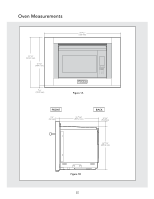
Oven Measurements 29 3/4 " (756 mm) 19 7/8" (504.8 mm) 19 1/16" (484.1 mm) 3/4" (19.05 mm) Figure 1A FRONT 1 1/4" (32 mm) 15 21/32" (397.6 mm) BACK 2 1/64" (51.18mm) 16 15/16" (430.2 mm) Figure 1B E5 - Viking VSOC530 | Installation Instructions - Page 6
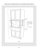
Clearances and Dimensions for Standard Surface Mount A. 27 15/16" cutout B. 18 1/8" cutout* C. 15 3/4" min. depth D. 33" min. height E. 4" F. 18" * Critical dimension Note: Platform must be able to support 70 lbs. Figure 2 E6 - Viking VSOC530 | Installation Instructions - Page 7
Installation Instructions for Standard Surface Mount 1. Mounting brackets should be installed with the 8 wood screws CL Square the mounting bracket to the opening and shelf 19 1/4" Note: Platform must be able to support 70 lbs. 90˚ Figure 3 Front of flange even with front of cabinet face E7 - Viking VSOC530 | Installation Instructions - Page 8
Installation Instructions for Standard Surface Mount WARNING Always take caution lifting heavy products. 2. Use a minimum of 2 people to lift and install oven. Place the oven adjacent to the cabinet opening, see Figure 4. Plug the power supply cord into the electrical outlet. 3. Carefully guide the - Viking VSOC530 | Installation Instructions - Page 9
must sit 1" back from the face of the cabinet. (allowing the face of the steam oven out 1/4") G B Platform edge Note: Platform must be able to support 70 lbs. Steam oven H J Cabinet face face Detail B Top View Note: the front surface of the platform must sit 1" back from the face of the - Viking VSOC530 | Installation Instructions - Page 10
Installation Instructions for Flush Mount 1. Install mounting brackets 19 1/4" with the 8 wood screws provided. Locate Square the mounting bracket to the opening and shelf 19 1/4" Note: Platform must be able to support 70 lbs. 90˚ Figure 9 Front of flange even with front of the platform E10 - Viking VSOC530 | Installation Instructions - Page 11
Installation Instructions for Flush Mount WARNING Always take caution lifting heavy products. 2. Use a minimum of 2 people to lift and install oven. Place the oven adjacent to the cabinet opening, see Figure 10. Plug the power supply cord into the electrical outlet. 3. Carefully guide the oven - Viking VSOC530 | Installation Instructions - Page 12
Model and serial number Before you call for service location Read the BEFORE YOU CALL and operating instruction sections in your Use and Care Manual. It may save you time and expense. The list includes common occurrences that are not the result of defective workmanship or materials in this oven. - Viking VSOC530 | Installation Instructions - Page 13
Guía de instalación Integrado Horno Combi Steam/Convect™ MVSOC530SS S - Viking VSOC530 | Installation Instructions - Page 14
INCENDIOS, DESCARGAS ELÉCTRICAS U OTROS DAÑOS PERSONALES INSTRUCCIONES IMPORTANTES DE SEGURIDAD • ADVERTENCIA: Si no se sigue exactamente el contenido de este manual, se podrá provocar un incendio o una descarga eléctrica que podrían causar daños a la propiedad, lesiones personales o la muerte - Viking VSOC530 | Installation Instructions - Page 15
futura. • Al igual que al usar cualquier horno que genera calor, hay precauciones de seguridad que debe seguir. Éstas se enumeran en el Manual de Uso y Cuidado. Lea todo y siga las instrucciones con cuidado. • Asegúrese de que su horno sea instalado y conectado a tierra correctamente por un - Viking VSOC530 | Installation Instructions - Page 16
Herramienta de instalación ARTÍCULO NOMBRE 1 Soporte de montaje izquierdo 2 Soporte de montaje derecho 3 Tornillos para madera 4 Pernos de montaje 5 Pernos de tope 6 Camisa de perno de tope 7 Mango 8 Llave Allen CANT. 1 1 8 4 2 2 1 1 CÓDIGO DE LA PIEZA LANGTB407MRP0 LANGTB408MRP0 - Viking VSOC530 | Installation Instructions - Page 17
Medidas del horno 19 7/8" (504.8 mm) 19 1/16" (484.1 mm) 29 3/4 " (756 mm) 3/4" (19.05 mm) Figura 1A FRENTE 1 1/4" (32 mm) PARTE TRASERA 15 21/32" (397.6 mm) 2 1/64" (51.18mm) 16 15/16" (430.2 mm) Figura 1B S5 - Viking VSOC530 | Installation Instructions - Page 18
Dimensiones y distancias para el montaje de la superficie estándar Permita un traslape de 7/8" Permita un traslape de 1" Permita un traslape de 7/8" Permita un traslape de 1" Ubicación sugerida del tomacorriente eléctrico A. Recorte de 27 15/16" B. Recorte de 18 1/8" * C. Profundidad mín. 15 - Viking VSOC530 | Installation Instructions - Page 19
Instrucciones de instalación para montaje en superficie estándar 1. Los soportes de montaje deben instalarse con los 8 tornillos para madera provistos, a 19 ¼" de distancia el uno del otro y centrados en la abertura del gabinete. Ubique la posición, marque el centro con un punzón y taladre el - Viking VSOC530 | Installation Instructions - Page 20
Instrucciones de instalación para montaje en superficie estándar ADVERTENCIA: Siempre tenga precaución al levantar productos pesados. 2. Use un mínimo de 2 personas para levantar e instalar el horno. Coloque el horno adyacente a la abertura del gabinete, vea la Figura 4. Enchufe el cable de - Viking VSOC530 | Installation Instructions - Page 21
Dimensiones y espacios libres para montar al ras Bloque añadido por el instalador del gabinete A 84" D C Bloque añadido por el instalador del gabinete Cara del horno H Cara del gabinete I de vapor Detalle A Ubicación sugerida del F tomacorriente Vista superior Nota: La superficie de - Viking VSOC530 | Installation Instructions - Page 22
Instrucciones de instalación para montaje al ras 1. Instale los soportes de montaje a 19 1/4" con los 8 tornillos para madera provistos. Ubique la posición, marque el centro con un punzón y taladre el agujero piloto de 1/8". Vea la Figura 9. Frente de la brida al ras con el frente de la superficie - Viking VSOC530 | Installation Instructions - Page 23
Instrucciones de instalación para montaje al ras ADVERTENCIA: Siempre tenga precaución al levantar productos pesados. 2. Use un mínimo de 2 personas para levantar e instalar el horno. Coloque el horno adyacente a la abertura del gabinete, vea la Figura 10. Enchufe el cable de alimentación en el - Viking VSOC530 | Installation Instructions - Page 24
. Esta lista incluye situaciones comunes que no son consecuencia de mano de obra o materiales defectuosos en este horno. Consulte en la garantía en su Manual de Uso y Cuidado el número de servicio de teléfono gratuito y la dirección. Por favor llame o escriba si tiene preguntas acerca de su producto - Viking VSOC530 | Installation Instructions - Page 25
Guide d'installation Four Combi Steam/Convect™encastré MVSOC530SS - Viking VSOC530 | Installation Instructions - Page 26
laisser ces instructions au consommateur qui doit les conserver pour l'usage d'un inspecteur local et pour référence ultérieure. INSTRUCTIONS DE MISE que les revêtements muraux et les armoires autour du four peuvent supporter la chaleur générée par l'appareil. • AVERTISSEMENT : Ne jamais laisser - Viking VSOC530 | Installation Instructions - Page 27
pas faire fonctionner le four et communiquer avec votre AGENT DE SERVICE AUTORISÉ. Notes importantes à la personne qui fera l'installation • le cordon d'alimentation fourni. Toujours vérifier les exigences des normes électriques. INSTRUCTIONS DE MISE À LA TERRE Cet appareil doit être mis à la terre - Viking VSOC530 | Installation Instructions - Page 28
Matériel d'installation ARTICLE NOM QTÉ 1 Bride de fixation gauche 1 2 Bride de fixation droite 1 3 Vis à bois 8 4 Boulons de montage 4 5 Boulons à épaulement 2 6 Fourreaux à boulon à épaulement 2 7 Poignée 1 8 Clé Allen 1 CODE DE LA PIÈCE LANGTB407MRP0 LANGTB408MRP0 - Viking VSOC530 | Installation Instructions - Page 29
Dimensions du four 29 3/4 po (756 mm) 19 7/8 po (504.8 mm) 19 1/16 po (484.1 mm) 3/4 po (19.05 mm) Figure 1A FAÇADE 1 1/4 po (32 mm) 15 21/32 po (397.6 mm) DOS 2 1/64 po (51.18mm) 16 15/16 po (430.2 mm) Figure 1B F5 - Viking VSOC530 | Installation Instructions - Page 30
de 2,2 cm (7/8 po) Prévoir un chevauchement de 2,5 cm (1 po) Figure 2 Emplacement de la prise électrique suggéré Remarque : la plateforme doit être en mesure de supporter 31,8 k (70 lb) A. découpe de 69,37 cm (27 15/16 po) B. découpe de 46 cm (18 1/8 po)* C. profondeur min. de 40 cm (15 3/4 po - Viking VSOC530 | Installation Instructions - Page 31
Instructions d'installation pour un montage en surface standard 1. Les brides de fixation doivent l'équerre avec l'ouverture et la tablette Remarque : La plateforme doit être en mesure de supporter 31,8 k (70 lb) 90˚ Figure 3 Devant de la bride à égalité avec le devant de la façade de l'armoire - Viking VSOC530 | Installation Instructions - Page 32
Instructions d'installation pour un montage en surface standard AVERTISSEMENT Veuillez toujours prendre des précautions lorsque vous soulevez des articles lourds. 2. Soulever et installer le four à l' - Viking VSOC530 | Installation Instructions - Page 33
dépasser la façade du four à vapeur vers l'extérieur de 6 mm [1/4 po]). G B Bord de la plateforme Remarque : la plateforme doit être en mesure de supporter 31,8 k (70 lb) Façade du four à vapeur H J Façade de l'armoire Détail B Vue du dessus Remarque : la surface de montage du bloc du - Viking VSOC530 | Installation Instructions - Page 34
Instructions d'installation pour le montage encastré 1. Installer les brides de fixation à 48,9 cm (19 1/ l'ouverture et la tablette 19 1/4 po Remarque : La plateforme doit être en mesure de supporter 31,8 k (70 lb) 90˚ Figure 9 Devant de la bride à égalité avec le devant de la plateforme F10 - Viking VSOC530 | Installation Instructions - Page 35
Instructions d'installation pour le montage encastré AVERTISSEMENT Veuillez toujours prendre des précautions lorsque vous soulevez des articles lourds. 2. Soulever et installer le four à l'aide d'un - Viking VSOC530 | Installation Instructions - Page 36
entretien pour obtenir le numéro sans frais et l'adresse du département de service. Veuillez appeler ou écrire si vous avez des questions concernant votre produit consulter le manuel d'utilisation et d'entretien pour les instructions de nettoyage. Viking Range, LLC 111 Front Street Greenwood
-
 1
1 -
 2
2 -
 3
3 -
 4
4 -
 5
5 -
 6
6 -
 7
7 -
8
-
9
-
10
-
11
-
12
-
13
-
14
-
15
-
16
-
17
-
18
-
19
-
20
-
21
-
22
-
23
-
24
-
25
-
26
-
27
-
28
-
29
-
30
-
31
-
32
-
33
-
34
-
35
-
36
 |
 |

Installation Guide
Built-in Combi Steam/Convect
™
Oven
MVSOC530SS