Viking VUBD140TRSS Use and Care Manual - Page 4
Wiring
 |
View all Viking VUBD140TRSS manuals
Add to My Manuals
Save this manual to your list of manuals |
Page 4 highlights
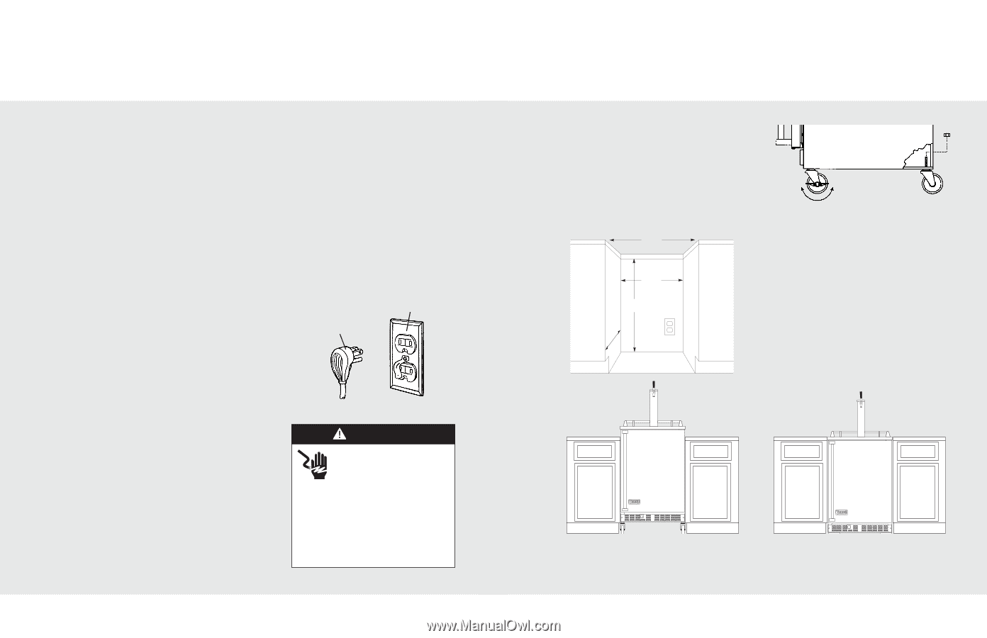
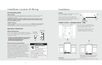
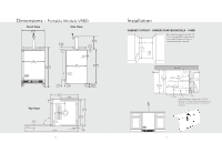
Installation Location & Wiring BUILT-IN INSTALLATION Select Location The proper location will ensure peak performance of your appliance. Choose a location where the unit will be out of direct sunlight and away from heat sources. Units with fan cooled condensers can be built-in. Unit should be operated in a properly ventilated area with ambient temperatures above 40°F (4.4°C) and below 110°F (43°C). Installation should be such that the cabinet can be moved for servicing if necessary. Cabinet Clearance Ventilation is required from the bottom front section of the unit. Keep this area open and clear of any obstructions. The adjacent cabinets and countertop can be built around the unit as long as no top trim or counter top is installed lower than the top of the hinge. ELECTRICAL CONNECTION Electrical Requirements A 115 volt, 60 Hz, AC only 15 amp fused electrical supply is required. (A time delay fuse or circuit breaker is recommended.) It is recommended that a separate circuit, serving only this appliance, be provided. Power Supply with 3-prong grounding plug • ELECTRICAL GROUND IS REQUIRED ON THIS APPLIANCE. • DO NOT UNDER ANY CIRCUMSTANCES REMOVE THE POWER SUPPLY CORD GROUND PLUG. • DO NOT USE AN EXTENSION CORD. Grounding type wall receptacle Recommended Grounding Methods For your personal safety, this unit must be grounded. This appliance is equipped with a power supply cord having a 3-prong grounding plug. To minimize possible shock hazard, the cord must be plugged into a mating 3-prong grounding type wall receptacle grounded in accordance with the National Electrical Code and local codes and ordinances. If the circuit does not have a grounding type receptacle, it is the responsibility and obligation of the customer to exchange the existing receptacle in accordance with the National Electrical Code and applicable local codes and ordinances. The third ground plug SHOULD NOT, under any circumstances, be cut or removed. All UL listed refrigerated products are equipped with this type of plug. WARNING ELECTRICAL SHOCK HAZARD Improper grounding can result in a risk of electric shock. Consult a qualified electrician if the grounding instructions are not completely understood, or if doubt exists as to whether the appliance is properly grounded. DO NOT use an extension cord. If the power supply cord is too short, have a qualified electrician install an outlet near the appliance. 6 Installation CASTERS Your beverage dispenser is equipped with four casters. The front two casters can be locked. For built-in applications, the four casters can be removed by removing the nut located inside the dispenser cabinet and then pulling the threaded caster spindle through the base of the unit. Lock and Unlock CABINET CUTOUT - PORTABLE MODELS - VRBD 24-3/4" (62.9 cm) *24" width for cabinet only. 24-1/4" (61.6 cm) needed for cabinet and door width clearance if door is recessed between cabinets. 24" (61.0 cm)* 35-9/16" (90.3 cm)** **35-9/16" (90.3 cm) height is without casters mounted to unit. 39-3/4" (101.0 cm) needed for height clearance with casters. (61.0 c24m)" NOTE: If removing casters for installation, the unit should be raised off the ground. This should be done with an approved material. (Consult local building codes for LEVEL UNIT approved material.) 1. After placing unit in position, check to make certain that the unit is level side to side and front to back. 2. Accurate leveling is essential for proper operation. 7
-
 1
1 -
 2
2 -
 3
3 -
 4
4 -
 5
5 -
 6
6 -
 7
7 -
 8
8 -
 9
9 -
 10
10 -
11
-
12
 |
 |