Viper VSS4000 Addendum - Page 2
Addendum: Owner's Guide - remote start system
 |
View all Viper VSS4000 manuals
Add to My Manuals
Save this manual to your list of manuals |
Page 2 highlights
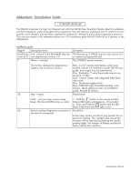
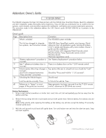
Addendum: Owner's Guide ! ATTENTION OWNER ! The VSS4000 integrates the Viper 5101 Remote Start with the VSM100 Viper SmartStart Module. Read this addendum and both installation guides thoroughly before beginning. They will help you understand how to combine the two systems, avoid mistakes, and smoothly complete the installation, verification and customer registration processes. The corrections made in this addendum address the 5101 Owner's guide (G4102V 2008-06) as it pertains to the VSN4000 kit. Owner's guide Page Description/error 9 What's included: Correction The VSS4000 system includes: This list has changed to integrate two systems, see Correction column. VSM100 Viper SmartStart module, wire harness, Quick reference User's & Installation guide. Module ID stickers. 5101V remote start/keyless entry main module, Owner's guide and this addendum Control Center with integrated Valet Override switch One five button/1way Supercode remote control Window decals Warranty registration cards 10 "Battery replacement" procedure is See "Battery Replacement" procedure below. incorrect. 11 Item 7 reference to battery door is There is no battery door on the 7153V remote control. incorrect. 13 Unlock section title at top of page is Top section title next to closed lock icon should be "Lock". incorrect. Aux/Trunk command instruction Should be "Press and Hold for 1 1/2 seconds". "Press one time" is incorrect. 16 Unlocking the Vehicle begins: Should read: Lock the vehicle normally. Press..... To Unlock the vehicle. Press..... All References to "beeps" on most Beep generator has been removed from the 7153V remote pages of the guide are incorrect. control, references to LED blinks are correct. Battery Replacement 1. Using a small slotted screwdriver or similar tool, insert into unit slot and gradually pry the top away from the bottom until free. 2. Remove the top along with the circuit board and turn both upside down. Remove battery from battery clip and replace. Note: Verify polarity while replacing the battery as the battery clip will also accept the battery if incorrectly inserted upside down. 3. With the unit top and circuit board still upside down. Turn unit bottom over and onto the other two parts. Snap unit back together. + + + + 2 © 2009 Directed Electronics. All rights reserved.
-
 1
1 -
 2
2
 |
 |
