Waring WSM7L Parts Diagram - Page 3
Illustration, Description
 |
View all Waring WSM7L manuals
Add to My Manuals
Save this manual to your list of manuals |
Page 3 highlights
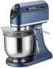
Catalog/Model WSM7L Illustration # 1 2 3 4 4a 5 6 7 8 9 10 11 12 13 14 15 16 17 18 19 20 21 22 23 24 25 26 27 28 29 30 31 32 33 Part # 037799 037800 037801 037802 037803 037804 037805 037806 037807 037808 037809 037811 037812 037813 037814 037815 037816 037817 037818 037819 037820 037821 037822 037823 037824 037404 037405 037407 037406 037408 037826 037827 037828 037829 Waring Factory Service Center 314 Ella T. Grasso Ave. Torrington, CT 06790 Tele. 1-800-269-6640 Fax 860-496-9017 www.waringcommercialproducts.com Description Top Cover Light Power Switch Potentiometer Potentiometer Knob Screw (2 required) Plastic Cover Screw (1 each clamp) Lead Clamp Interlock with Bracket Screw with Washers (2 required) Motor Hex Bolt with Washers (4 required) Screw (3 required) Mixer Head Bottom Screen Screw (2 required) Screw (2 required) Screw Spring Washer Bowl Pad Stand Plum Wrench Shaft Cover (2 required) Shaft Reset Switch Cord Screw Clamp Hex Nut Ground Screw Lock Washer Ground Tag Junction Box Page 3 of 4
-
 1
1 -
 2
2 -
 3
3 -
 4
4
 |
 |
