Waring WSM7L Parts Diagram - Page 4
Catalog/Model
 |
View all Waring WSM7L manuals
Add to My Manuals
Save this manual to your list of manuals |
Page 4 highlights
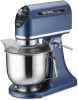
Catalog/Model WSM7L Illustration # 34 35 36 37 38 39 40 41 42 43 44 45 46 47 48 49 50 51 Brown LPeCaBd Bcoonarndected to Gray LPeaCdBcBoonanredcted to GreeBnlaLcekadCocordnnLeecatded to YeBlllouwe LLPePeCaCadBdBcBcBoooonnaanrnrdeedcctteeddttoo Pink LReeasdetcSownnitecchted to Waring Factory Service Center 314 Ella T. Grasso Ave. Torrington, CT 06790 Tele. 1-800-269-6640 Part # 037830 037831 037832 037833 037834 037835 037836 037837 037836 037838 037839 037840 037841 037842 037843 037844 037810 037825 Fax 860-496-9017 www.waringcommercialproducts.com Description PCB Board Metal Plate Nylon Screw (4 required holds junction box to metal plate) Screw (3 required holds 3 of corners of PCB to metal plate) Screw with Washers (holds the last corner of PCB to metal plate) Spacer (holds the last corner of PCB to metal plate) Hex Nut (holds the last corner of PCB to metal plate) Screw with Washers (2 required holds mosfets on PCB to metal plate) Hex Nut (2 required holds mosfets on PCB to metal plate) Ceramic Seal (holds mosfets on PCB to metal plate Large Rubber Mat (under large mosfet) Small Rubber Mat (under small mosfet) Push Spacer Stand Offs (3 required under 3 of corners of PCB) Screw (2 required) Bottom Plate with Feet Screw (5 required) Gray Rubber Sleeve with Leads White Rubber Sleeve with Leads White LPeCadB cBoonanrdected to 50 Black Lead connected to Light Black Lead connected to Light White LPeCadB cBoonanrdected to Brown LPeCaBd Bcoonarndected to Gray LPeaCdBcBoonanredcted to Pink LPeaCdBcBoonanredcted to GrWeehnitLeeRadubcboenrnSelceteevdeto Blue LePaCdBcBoonanredcted to Yellow LPeCaBdBcoonarndected to Red Lead connected Green Lead on Gray Rubber Sleeve 51 Blue Lead connected to PCB Board Red Lead connected to Interlock switch Blue Lead connected to Interlock switch Page 4 of 4
-
 1
1 -
 2
2 -
 3
3 -
 4
4
 |
 |
