Waring WWB5G Parts Diagram - Page 2
Description
 |
View all Waring WWB5G manuals
Add to My Manuals
Save this manual to your list of manuals |
Page 2 highlights
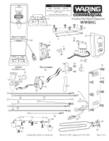
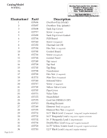
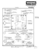
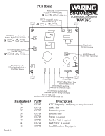
Catalog/Model WWB5G Illustration# 1 2 3 4 5 6 7 8 9 10 11 12 13 14 15 16 17 18 19 20 21 22 23 24 25 26 27 28 29 30 31 32 33 34 Page 2 of 4 Part# 037696 037697 037698 037717 037699 037704 037163 037153 037154 037700 037701 037702 037149 037728 037703 037708 037709 013731 037165 037717 037705 037707 037771 037172 037173 037715 037169 037170 037731 037733 037732 037730 037729 037710 Waring Factory Service Center 314 Ella T. Grasso Ave. Torrington, CT 06790 Tele. 1-800-269-6640 Fax 860-496-9017 www.waringcommercialproducts.com Description OverflowTray (metal) Overflow Tray (plastic) Tank Top Cover Screw (6 required) Tank Top Cover Gasket PCB Board Screw (4 required) Thermal Cut Off Hex Nut (2 required) Control Board Screw (4 required) Control Panel Tap (spigot) Tap Seal Tap Ring Transformer Hex Nut (2 required) Wire Ties (5 required) Solenoid Valve Screw (2 required) Yellow Valve Cover Pipe Cover Valve Tube Strain Relief Cord Set (NEMA 5-15P) Heating Element Element Seal (2 required) Element Hex Nut (2 required) 16.5" Black Lead (2 required 1 ring and 1 regular terminal) 16.5" Burgundy Lead (1 ring and 1 regular terminal) 16 .5" Burgundy Lead (2 ring terminals) Double Blue Lead (2 ring and 1 regular terminal) 16.75" Yellow/Green Lead (1 ring and 1 regular terminal) 12.5" Black Lead (1 ring and 1 regular terminal
-
 1
1 -
 2
2 -
 3
3 -
 4
4
 |
 |