Waring WWB5G Parts Diagram - Page 4
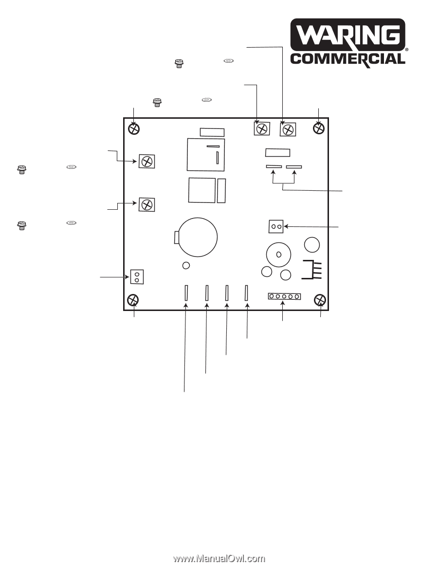
PCB Board
 |
View all Waring WWB5G manuals
Add to My Manuals
Save this manual to your list of manuals |
Page 4 highlights
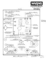
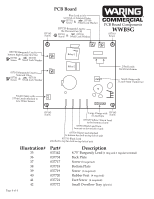
PCB Board Blue Lead to left terminal on Solenoid Valve 037701 Screw & 037158 Small Lock Washer 037163 Screw 037733-BurgundyLead to the Thermal Cut Off 037701 Screw & 037158 Small Lock Washer PCB Board Components WWB5G 037163 Screw 037732-Burgundy Lead to bottom Right Large Hex Nut 037701 Screw & 037158 Small Lock Washer 037142-Burgundy Lead to Solenoid Valve 037701 Screw & 037158 Small Lock Washer Relay1 Relay2 2 Red Leads fromTransformer Small Clamp with 2 Leads from Tranformer Small Clamp with 2 Thin Leads attached to Low Water Sensor 037163 Screw Large Clamp with 6 Lead Tape 037163 Screw 037729-Yellow/Green Lead to the bottom of unit 037710-Black Lead from hex nut on lower left of unit 037731-Black Lead attached to bottom hex bolt on top left of unit 037731-Black Lead attached to top hex bolt on top left of unit Illustration# 35 36 37 38 39 40 41 42 Part# 037142 037734 037717 037718 037719 037720 037721 037772 Description 8.75" Burgundy Lead (1 ring and 1 regular terminal) Back Plate Screw (8 required) Bottom Plate Screw (6 required) Rubber Feet (4 required) Feet Screw (4 required) Small Overflow Tray (plastic) Page 4 of 4
-
 1
1 -
 2
2 -
 3
3 -
 4
4
 |
 |