Weider 1033 Ultramax Be English Manual - Page 7
Seat Assembly
 |
View all Weider 1033 Ultramax Be manuals
Add to My Manuals
Save this manual to your list of manuals |
Page 7 highlights
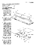
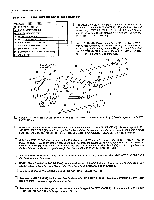
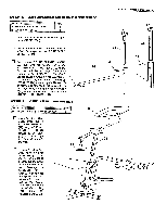
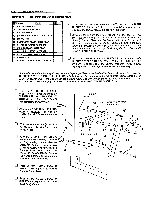
STEP 2 BACKREST & SEAT ASSEMBLY PAGE 6 WADER SPORTING GOODS 30 5/16' NYLON LOCK NUT 32 5/16" X 31/4" HEX HEAD BOLT 41 1/4" X 3/4' ROUND HEAD MACHINE SCREW 65 5/16" I.D. X 13 /32" LONG METAL SPACER u Turn the BACKREST (4) over to expose the threaded holes. Position the LONG ANGLE' IRONS (6) so that the flat side faces the inside of the Backrest. Fasten with 1/4" X 3/4" ROUND HEAD MACHINE SCREWS (41). DO NOT COMPLETELY TIGHTEN THESE SCREWS AT THIS TIME! 1 1 6 2 41 41 0 6 6 The bottom end of the BACKREST (4) is the end that the LONG ANGLE IRONS (6)_ extend past. This is the end that is assembled to the MAIN FRAME (3). c 4 Straddle the LONG ANGLE IRONS (6) on the BACKREST (4) over the bolt hole location on the MAIN FRAME (3). Assemble a 5/16" X 3 1/4" HEX HEAD BOLT (32) into the large hole at the very end of one of the Long Angle Irons and then into a 5/16" I.D. X 13/32" LONG METAL SPACER (65). The Hex Head Bolt will then go all the way through the Main Frame. As the Bolt comes out of the Main Frame on the other side, place another 13/32" LONG METAL SPACER (65) onto the Bolt and push the Bolt the rest of the way through into the opposite Long Angle Iron. Secure with a 5/16" NYLON LOCK NUT (30). TIGHTEN ALL SCREWS ON THE BACK OF THE BACKREST AT THIS TIME. u Align the SEAT (5) onto the Seat Bracket on the MAIN FRAME (3) and attach with 1/411 X 3/4N ROUND HEAD MACHINE SCREWS (41) by bolting up through the Seat Bracket and then into the Seat. 5 6 30 65 32 65 3 41 ti 41 41 • SEAT BRACKET 0
-
 1
1 -
 2
2 -
 3
3 -
 4
4 -
 5
5 -
 6
6 -
 7
7 -
 8
8 -
 9
9 -
 10
10 -
 11
11 -
 12
12
 |
 |
