Weider 1033 Ultramax Be English Manual - Page 9
Adjustable Upright Assembly
 |
View all Weider 1033 Ultramax Be manuals
Add to My Manuals
Save this manual to your list of manuals |
Page 9 highlights
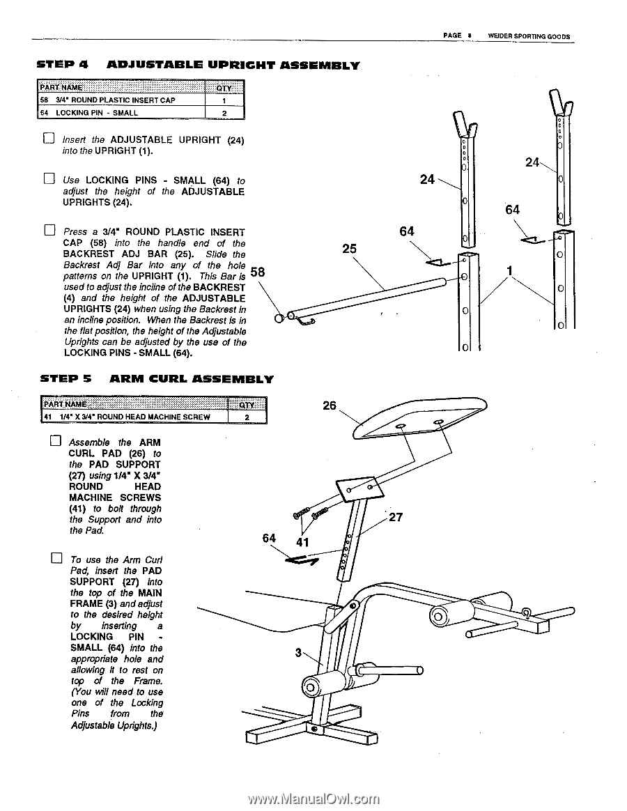
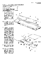
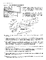
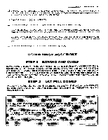
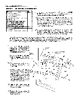
PAGE 8 WEIDER SPORTING GOODS STEP 4 ADJUSTABLE UPRIGHT ASSEMBLY PART NAME TY 58 3/4' ROUND PLASTIC INSERT CAP 1 64 LOCKING PIN - SMALL 2 u Insert the ADJUSTABLE UPRIGHT (24) into the UPRIGHT (1). Use LOCKING PINS - SMALL (64) to adjust the height of the ADJUSTABLE UPRIGHTS (24). 0 0 24 0 u Press a 3/4" ROUND PLASTIC INSERT CAP (58) into the handle end of the BACKREST ADJ BAR (25). Slide the Backrest Adj Bar into any of the hole patterns on the UPRIGHT (1). This Bar is 58 used to adjust the incline of the BACKREST (4) and the height of the ADJUSTABLE UPRIGHTS (24) when using the Backrest in an incline position. When the Backrest is in the flat position, the height of the Adjustable Uprights can be adjusted by the use of the LOCKING PINS - SMALL (64). 64 25 STEP 5 ARM CURL ASSEMBLY PART 26 41 1/4" X 3/4" ROUND HEAD MACHINE SCREW 2 Assemble the ARM CURL PAD (26) to the PAD SUPPORT (27) using 1/4" X 3/4" ROUND HEAD MACHINE SCREWS (41) to bolt through the Support and into the Pad. u To use the Arm Curl Pad, insert the PAD SUPPORT (27) into the top of the MAIN FRAME (3) and adjust to the desired height by inserting a LOCKING PIN SMALL (64) into the appropriate hole and allowing it to rest on top of the Frame. (You will need to use one of the Locking Pins from the Adjustable Uprights.) • 27 64 41 3 0 e 24 0 64
-
 1
1 -
2
-
3
-
 4
4 -
 5
5 -
 6
6 -
 7
7 -
 8
8 -
 9
9 -
 10
10 -
 11
11 -
 12
12
 |
 |