Weider 9900i Uk Manual - Page 10
Identify the Burn Cable 45.
 |
View all Weider 9900i manuals
Add to My Manuals
Save this manual to your list of manuals |
Page 10 highlights
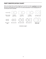
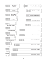
7. Apply some of the included grease to an M10 x 57mm Bolt Set (80). 7 Orient the Leg Lever (13) so that the high end of the bracket is in the location shown. Attach the Leg Lever (13) to the Leg (10) with the M10 x 57mm Bolt Set (80). Make sure that the barrel of the Bolt Set is inserted through both sides of the bracket on the Leg. 80 13 Grease 80 10 High End 8. See the CABLE DIAGRAM on page 38 to identify the cables as you assemble them. 8 Identify the Burn Cable (45). Identify the four Burn Pulleys (68), the three V-pulleys (not shown), and the twenty Pulleys (not shown). Route the threaded end of the Burn Cable (45) through the bracket on the Base (1) as shown. Attach a Burn Pulley (68) over the Burn Cable (45) inside the bracket on the Base (1) with an M10 x 63mm Bolt (89), two 12.7mm Spacers (73), and an M10 Locknut (74). Threaded 74 End 45 73 1 68 73 89 9. Attach a second Burn Pulley (68) over the Burn Cable (45) inside the bracket on the Base (1) 9 with an M10 x 63mm Bolt (89), two 12.7mm Spacers (73), and an M10 Locknut (74). 74 45 73 1 68 73 89 10
-
 1
1 -
2
-
3
-
4
-
 5
5 -
 6
6 -
 7
7 -
 8
8 -
 9
9 -
 10
10 -
 11
11 -
 12
12 -
 13
13 -
 14
14 -
 15
15 -
16
-
17
-
18
-
19
-
20
-
21
-
22
-
23
-
24
-
25
-
26
-
27
-
28
-
29
-
30
-
31
-
32
-
33
-
34
-
35
-
36
-
37
-
38
-
39
-
40
-
41
-
42
-
43
-
44
-
45
-
46
-
47
-
48
 |
 |
