Weider 9900i Uk Manual - Page 7
Assembly
 |
View all Weider 9900i manuals
Add to My Manuals
Save this manual to your list of manuals |
Page 7 highlights
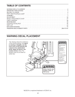
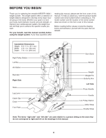
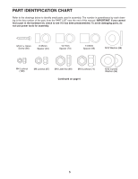
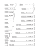
ASSEMBLY To make assembly easier, carefully read the following information and instructions: • Assembly requires two persons. • Because of its weight and size, assemble the weight system in the location where it will be used. Make sure that there is enough clearance to walk around the weight system. • Place all parts in a cleared area and remove the packing materials. Do not dispose of the packing materials until assembly is completed. • For help identifying small parts, use the PART IDENTIFICATION CHART on pages 5 and 6. • The following tools (not included) may be required for assembly: two adjustable wrenches one rubber mallet one standard screwdriver one Phillips screwdriver Assembly may be more convenient if you have a socket set, a set of open-end or closed-end wrenches, or a set of ratchet wrenches. 1. To make assembly easier, read the assembly tips in the box above. Orient the Base (1) and the Side Stabilizers (2) as shown. Attach the Side Stabilizers (2) to the Base (1) with two M10 x 95mm Bolts (78) and two M10 Locknuts (74). Do not fully tighten the Locknuts yet. 1 2 74 74 1 78 2 78 Warning Decal 2. Orient the U-stabilizer (3) and the Foot Plate (4) as shown. Make sure that the textured side of 2 3 the Foot Plate is facing upward. 82 Attach the Foot Plate (4) to the U-stabilizer (3) with two M8 x 65mm Button Screws (82). Do not overtighten the Screws; the Foot Plate 4 must pivot easily. 82 7
-
 1
1 -
 2
2 -
 3
3 -
 4
4 -
 5
5 -
 6
6 -
 7
7 -
 8
8 -
 9
9 -
 10
10 -
 11
11 -
 12
12 -
13
-
14
-
15
-
16
-
17
-
18
-
19
-
20
-
21
-
22
-
23
-
24
-
25
-
26
-
27
-
28
-
29
-
30
-
31
-
32
-
33
-
34
-
35
-
36
-
37
-
38
-
39
-
40
-
41
-
42
-
43
-
44
-
45
-
46
-
47
-
48
 |
 |
