Weider Club 540 English Manual - Page 6
Attach the Rear Uprights 2 to the Left and Right
 |
View all Weider Club 540 manuals
Add to My Manuals
Save this manual to your list of manuals |
Page 6 highlights
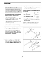
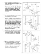
3. Identify the two Rear Uprights (2), which are slightly shorter and have less holes than the Front Uprights (not shown). Attach the Rear Uprights (2) to the Left and Right Bases (5, 6) using four M10 x 78mm Bolts (25) and four M10 Nylon Locknuts (26). Do not tighten the Nylon Locknuts yet. Make sure the Uprights are oriented as shown, with the adjustment holes on the indicated side near the bottom. 4. Tap a 2mm Thick 60mm Square Inner Cap (43) into the top of each Front Upright (1). Attach a Front Upright (1) and two Joint Plates (14) to the Left Base (6) using four M10 x 78mm Bolts (25) and four M10 Nylon Locknuts (26). Do not tighten the Nylon Locknuts yet. Make sure that the Front Upright is oriented so the holes near the bottom of the Front Upright and the holes in the Joint Plates line up. If they do not line up, turn the Front Upright upside-down. Make sure the Front Upright is turned so the adjustment holes are facing the Rear Upright (2). Attach the other Front Upright (1) to the Right Base (5) in the same manner. 5. Attach the Chin-up Bar (12) and two Joint Plates (14) to the Front Uprights (1) using four M10 x 78mm Bolts (25) and four M10 Nylon Locknuts (26). Do not tighten the Nylon Locknuts yet. 3 2 25 Adjustment Holes 26 2 5 4 1 26 25 6 43 Adjustment Holes 5 25 14 5 26 14 12 25 1 25 1 6 14 26 26 14 6. Press a 1.5mm Thick 60mm Square Inner Cap (21) into the Left Frame (3). Attach the Left 6 4 Frame to the left Uprights (1, 2) using four M10 x 78mm Bolts (25) and four M10 Nylon Locknuts (26). Do not tighten the Nylon Locknuts yet. Assemble the Right Frame (4) to the right Uprights (1, 2) in the same manner. 1 6 1 26 2 3 25 25 26 1 21 26 2
-
 1
1 -
 2
2 -
 3
3 -
 4
4 -
 5
5 -
 6
6 -
 7
7 -
 8
8 -
 9
9 -
 10
10 -
 11
11 -
 12
12 -
13
-
14
-
15
-
16
 |
 |
