Weider Pro 136 English Manual - Page 8
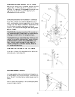
the Support Tube 7. Set the Support Tube into
 |
View all Weider Pro 136 manuals
Add to My Manuals
Save this manual to your list of manuals |
Page 8 highlights
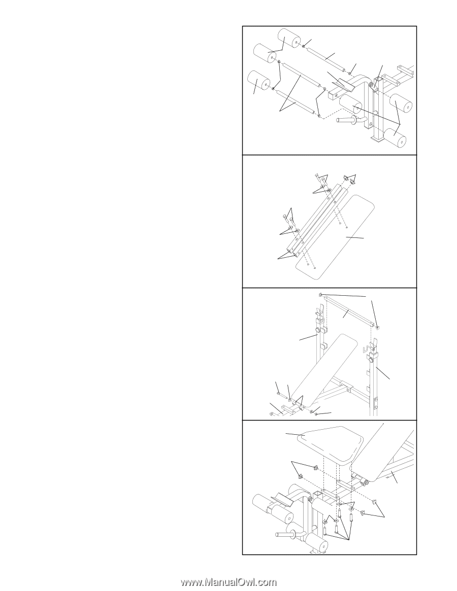
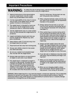
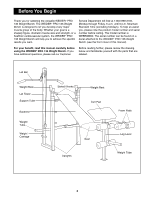
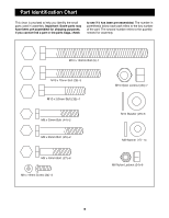
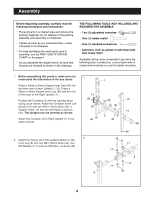
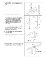
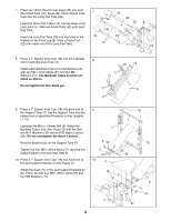
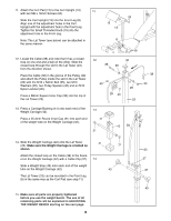
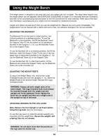
7. Press two 19mm Round Inner Caps (33) into each Short Pad Tube (10). Press two 19mm Round Inner Caps into the Long Pad Tube (28). Insert the Short Pad Tubes (10) into the holes in the Leg Lever (4). Slide two Foam Pads (22) onto each Pad Tube. Insert the Long Pad Tube (28) into the holes in the bracket on the Front Leg (8). Slide a Foam Pad (22) onto each end of the Long Pad Tube. 7 22 33 22 10 33 28 33 4 33 8 22 8. Press a 1Ó Square Inner Cap (18) into the indicated 8 end of each Backrest Tube (5). Attach each Backrest Tube (5) to the Backrest (6) with two M8 x 40mm Bolts (27) and two M8 Washers (17). The Backrest Tubes must be oriented as shown. 27 18 17 27 Do not tighten the four Bolts yet. 17 6 5 9. Press a 1Ó Square Inner Cap (18) into each end of the Support Tube (7). Set the Support Tube into the highest set of adjustment brackets on the Uprights (1, 15). Lubricate the M10 x 130mm Bolt (9). Attach the Backrest Tubes (5) to the Frame (2) with the Bolt, two M10 Washers (29) and an M10 Nylon Locknut (30). Do not overtighten the Nylon Locknut. Rest the Backrest (6) on the Support Tube (7). Tighten the four M8 x 40mm Bolts (27) securing the support tubes to the seat (see Step 8). 10. Press a 1Ó Square Inner Cap (18) into each end of the seat support brackets on the Frame (2). Attach the Seat (11) to the seat support brackets on the Frame (2) with four M8 x 40mm Bolts (27) and four M8 Washers (17). 9 18 7 1 9 29 15 5 2 29 30 10 11 18 17 17 2 18 27 8
-
 1
1 -
2
-
 3
3 -
 4
4 -
 5
5 -
 6
6 -
 7
7 -
 8
8 -
 9
9 -
 10
10 -
 11
11 -
 12
12 -
 13
13 -
14
-
15
-
16
 |
 |