Weider Pro 202 Bench English Manual - Page 7
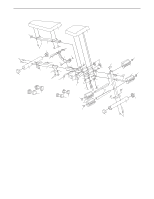
Attach the Silver Stabilizer 4 to the Rear Leg 3
 |
View all Weider Pro 202 Bench manuals
Add to My Manuals
Save this manual to your list of manuals |
Page 7 highlights
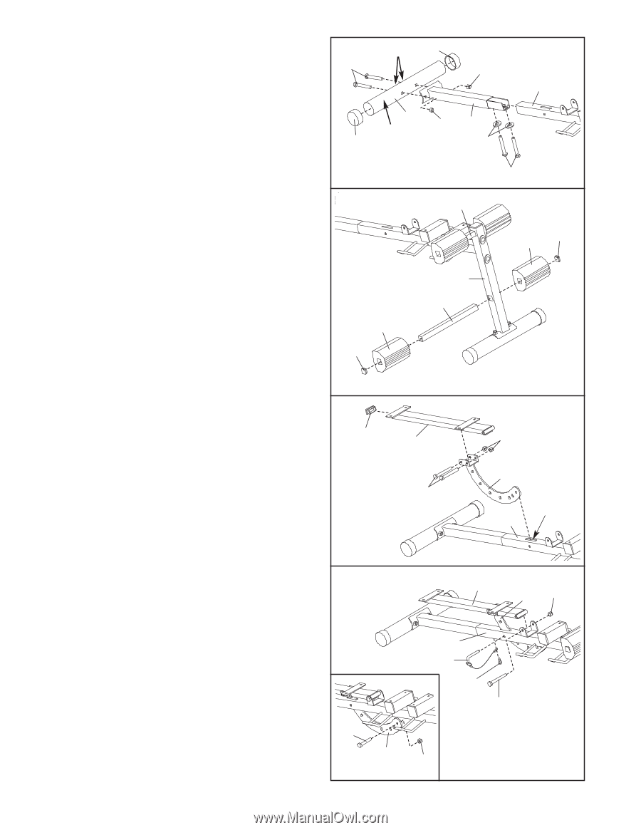
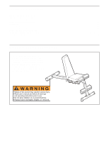
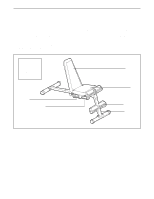
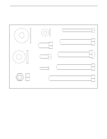
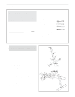
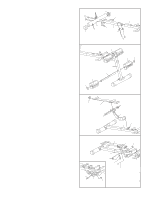
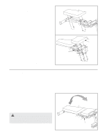
3. Press two 50mm Round Outer Caps (12) onto the ends of the Silver Stabilizer (4). Attach the Silver Stabilizer (4) to the Rear Leg (3) with two M10 x 63mm Carriage Bolts (18) and two M10 Nylon Locknuts (19). Be sure the indents, the warning decal, and the Rear Leg are oriented as shown. Do not tighten the Locknuts yet. Attach the Rear Leg (3) to the Frame (1) with two M10 x 20mm Bolts (25) and two M10 Washers (20). Tighten the M10 Nylon Locknuts (19) used in steps 1-3. 4. Press two 25mm Square Inner Caps (11) into a Pad Tube (10). Slide the Pad Tube (10) into the Front Leg (2). Wet the ends of the Pad Tube with soapy water. Slide two Foam Pads (9) onto the ends of the Pad Tube. Repeat this step with the other Pad Tube (10). 3 Indents 12 18 19 1 4 Warning 12 Decal 19 3 20 25 4 10 11 9 9 11 2 10 5. Press a 25mm x 50mm Inner Cap (15) into the Backrest Frame (5). Attach the Pivot Bracket (6) to the Backrest Frame (5) with two M10 x 70mm Bolts (26) and two M10 Nylon Locknuts (19). Do not tighten the Locknuts yet. 5 15 Insert the Pivot Bracket (6) into the slot in the Frame (1). 6. Lubricate the M10 x 85mm Bolt (23) with grease. Attach the Backrest Frame (5) to the Frame (1) with the Bolt and an M10 Nylon Locknut (19). Do not overtighten the Locknut; the Backrest 6 Frame must be able to pivot easily. Attach the tether on the Locking Pin (21) to the bottom of the Frame (1) with the M4 x 16mm Screw (28). Insert the Locking Pin (21) into the Frame (1) and through an adjustment hole in the Pivot Bracket (6). See the inset drawing. Attach an M10 x 20mm Bolt (25) and an M10 Nylon Locknut (19) to the last hole in the Pivot Bracket (6). Tighten the M10 Nylon Locknuts (19) used in step 5. 25 6 7 5 19 6 26 Slot 1 5 6 19 1 21 28 23 19
-
 1
1 -
 2
2 -
 3
3 -
 4
4 -
 5
5 -
 6
6 -
 7
7 -
 8
8 -
 9
9 -
 10
10 -
 11
11 -
 12
12
 |
 |