Weider Pro 800 English Manual - Page 8
Note: The Backrest
 |
View all Weider Pro 800 manuals
Add to My Manuals
Save this manual to your list of manuals |
Page 8 highlights
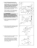
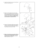
7. Lubricate an M10 x 72mm Bolt (40). Attach the Leg Lever (4) to the Front Leg (8) with the Bolt and an M10 Nylon Locknut (19). Attach the Weight Tube (41) to the Leg Lever (4) with the M8 x 58mm Bolt (39), two M8 Washers (38), the Spacer (37), and an M8 Nylon Locknut (13). Note: The Spacer will fit tightly inside of the Leg Lever. 7 19 4 39 38 37 8 40 Lubricate 8. Press four 1" Square Inner Caps (12) into the indicated ends of the Backrest Tubes (5, 42). Press two 1" x 2" Inner Caps (36) into the ends of the adjustment tubes. With the wide end of the Backrest (6) positioned as shown, attach the Backrest Tubes (5, 42) to the Backrest with four M6 x 38mm Screws (16) and four M6 Washers (25). Note: The Backrest Tubes and Backrest must be oriented exactly as shown. 9. Lubricate the M10 x 178mm Bolt (17). Attach the Backrest (6) to the Frame (2) with the Bolt, two M10 Washers (24), and an M10 Nylon Locknut (19). Secure the Backrest (6) by sliding the Adjustment Pin (32) through one of the three sets of holes in the adjustment tubes and the indicated hole in the Frame (2). Secure the Adjustment Pin with the Pin Clip (14). Make sure the Adjustment Pin (32) is completely inserted through both holes in the adjustment tubes and the Frame (2). 10. With the wide end of the Seat (11) positioned as shown, attach the Seat to the brackets on the Frame (2) with four M6 x 16mm Screws (15). 41 38 13 8 6 Wide End 5 12 25 16 36 9 32 Lubricate 24 17 24 10 11 Wide End 12 25 42 16 Adjustment Tubes 25 16 6 Adjustment Tubes 2 19 14 2 15 8
-
 1
1 -
2
-
 3
3 -
 4
4 -
 5
5 -
 6
6 -
 7
7 -
 8
8 -
 9
9 -
 10
10 -
 11
11 -
 12
12 -
 13
13 -
14
-
15
-
16
 |
 |
