Weider Pro 9350 English Manual - Page 10
overtlghten
 |
View all Weider Pro 9350 manuals
Add to My Manuals
Save this manual to your list of manuals |
Page 10 highlights
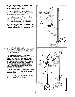
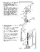
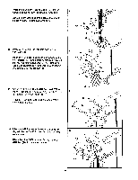
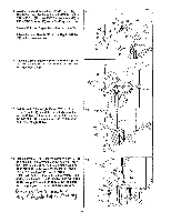
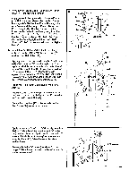
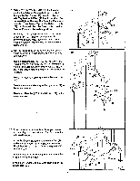
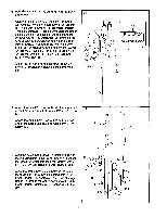
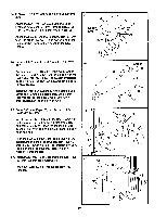
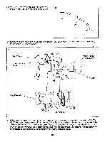
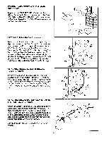
18. Slide a 3/8" Flat Washer (64) onto the threaded shaft of the Selector Plate (49). Insert the shaft through the Arm Frame (41) from the indicated side. Tighten the 3/8" Nut (105) onto the shaft. Do not overtlghten the Nut; the Selector Plate must be able to turn freely. Tighten the Selector Knob (24) onto the shaft. Turn the Selector Knob so the Selector Plate is in the vertical position. Thread a 1 1/4" Tap Screw (8) into the upper end of each Arm (27). Tighten or loosen the Tap Screws until there is no movement in the Arms when the Selector Plate (49) is turned to the horizontal position. 19. Wet the lower ends of the Arms (27) with soapy water. Slide an 8" Foam Pad (28) about halfway up each Arm. Insert a Short Handle (47) into the right Arm (27). Attach the Short Handle to the right Arm with a 5/16" x 2 1/4" Bolt (23), two 5/16" Flat Washers (45), a 1/2" x 3/8" Bushing (57) and a 5/16" Nylock Nut (4) as shown. Press a 1" Round Cap (43) into the Short Handle (47). Attach another Handle (47) to the right Arm (27) in the same manner. Attach two Handles (47) to the left Arm (27) in the same manner. 18 to 19 28 24 27 V 105 8 41 27 49 64 27 27 47 28 43 4 4 57 23 45 47 47 20. Extend the two Arm Shocks (25). Apply a liberal amount of grease around each Arm Shock in the indicated location. Insert the Shock Bar (26) into the Pivot Arm (75) and center it. Attach an Arm Shock (25) to the Shock Bar with a 1/4" x 1 1/4" Bolt (66) and 1/4" Nylock Nut (5). Attach the other Arm Shock (25) to the Shock Bar (26) in the same manner. Press a 3/4" Outer Cap (65) onto each end of the Shock Bar (26). 20 66 25 65 5 26 66 75 65 10 25 Grease
-
 1
1 -
2
-
3
-
4
-
 5
5 -
 6
6 -
 7
7 -
 8
8 -
 9
9 -
 10
10 -
 11
11 -
 12
12 -
 13
13 -
 14
14 -
 15
15 -
16
-
17
-
18
-
19
-
20
-
21
-
22
-
23
-
24
 |
 |
