Weider Pro Xt75 English Manual - Page 8
Press a 60mm Square Inner Cap 29 into the Left - system
 |
View all Weider Pro Xt75 manuals
Add to My Manuals
Save this manual to your list of manuals |
Page 8 highlights
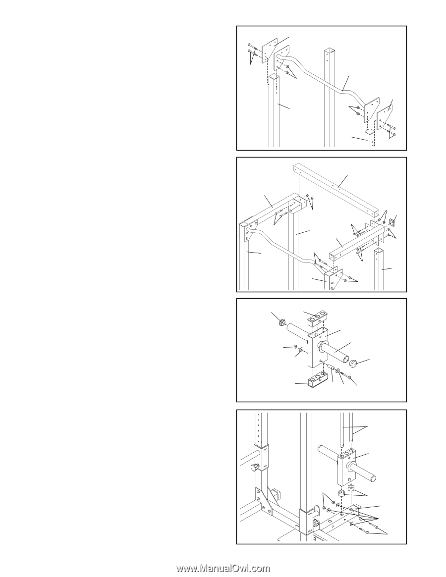
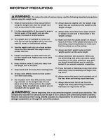
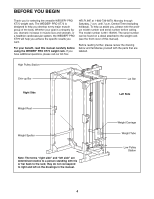
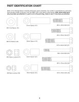
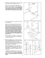
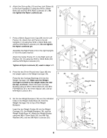
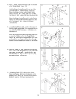
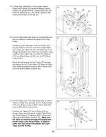
6. Attach the Chin-up Bar (13) and two Joint Plates (6) to the Front Uprights (7) using four M10 x 78mm 6 6 Bolts (33) and four M10 Nylon Locknuts (31). Do not tighten the Nylon Locknuts yet. 33 13 31 6 7 31 7. Press a 60mm Square Inner Cap (29) into the Left Frame (12). Attach the Left Frame to the left Uprights (7, 8) using four M10 x 78mm Bolts (33) and four M10 Nylon Locknuts (31). Do not tighten the Nylon Locknuts yet. Assemble the Right Frame (10) to the right Uprights (7, 8) in the same manner. Attach the Center Frame (11) to the Right and Left Frames (10, 12) using four M10 x 78mm Bolts (33) and four M10 Nylon Locknuts (31). Tighten all Nylon Locknuts (31) used in steps 1-7. 8. Press the two 51mm Round Inner Caps (46) into the weight tubes on the Weight Carriage (15). Press the two Carriage Bushings (16) into the Weight Carriage (15). Make sure the Weight Carriage is turned so the weight tubes are near the top, as shown. Attach the lower Carriage Bushing using an M10 x 66mm Bolt (37), two M10 Flat Washers (41), the 51mm Spacer (43), and an M10 Nylon Locknut (31). 7 10 33 7 7 33 11 31 33 8 12 33 33 7 31 31 29 31 8 8 46 16 31 41 16 15 Weight Tube 46 43 41 37 9. Set the two Weight Bumpers (18) over the indicated holes in the Weight Guide Base (4). Hold the 9 Weight Carriage (15) on top of the Weight Bumpers. Insert the two Weight Guides (9) into the Weight Carriage (15), the Weight Bumpers (18), and the Weight Guide Base (4). Attach the Weight Guides using two M8 x 72mm Bolts (35), four M8 Flat Washers (40), and two M8 Nylon Locknuts (32). 8 9 15 32 18 4 40 35
-
 1
1 -
2
-
 3
3 -
 4
4 -
 5
5 -
 6
6 -
 7
7 -
 8
8 -
 9
9 -
 10
10 -
 11
11 -
 12
12 -
 13
13 -
14
-
15
-
16
-
17
-
18
 |
 |